The pump mechanical neutral adjustment sets the position of the servo piston and pump swash plate relative to the hydraulic controller. This procedure should be followed if the hydrostatic pump has been disassembled for servicing the servo piston and the setting has been disrupted.
Place the loader on jackstands. (See Procedure on Page 10-10-1.)
Raise the lift arms, and install an approved lift arm support device. (See Installing on Page 10-20-1.)
Raise the operator cab. (See Raising on Page 10-30-2.)
Connect the remote start tool. (See REMOTE START TOOL KIT-MEL1563 on Page 10-60-1.)
Disconnect the swash plate angle sensors in the electrical harness. This prevents unwanted swash plate movement error codes from occurring during adjustments. Disconnecting the sensors does not have to be done directly at the sensor, follow the harness back to find an accessible connector to disconnect.
Disconnect the speed sensors located on the top of the motor carriers. This prevents uncommanded wheel movement error codes from occurring during adjustments.
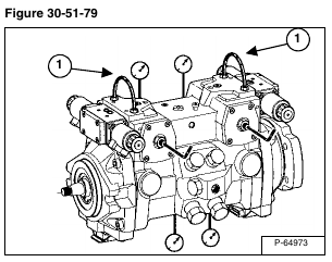
Connect a hydraulic hose (Item 1) [Figure 30-51-79] between port X1 and port X2 on each side of the hydrostatic pump, to equalize the pressures on both ends of the servo pistons.
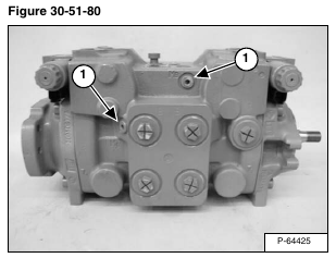
Remove the plugs (Item 1) [Figure 30-51-80] from the MB ports on the front side of the pump, and install 7500 PSI (241 bar) pressure gauges.
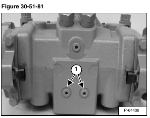
Remove the plugs (Item 1) [Figure 30-51-81] from the MA ports on the bottom of the pump, and install 7500 PSI pressure gauges.
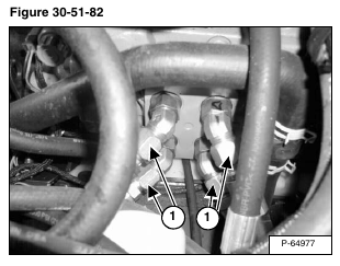
Remove drive hoses from the A and B ports (Item 1) [Figure 30-51-82]. Plug the ports with metal caps. The caps must be able to handle at least 7500 PSI. Plugging the A and B ports eliminates leakage at the drive motors from causing errors in the pump mechanical neutral setting.
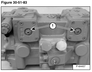
Loosen the pump neutral adjustment lock nut (Item 1) [Figure 30-51-83].
Start the loader using the remote start tool and run at an idle.
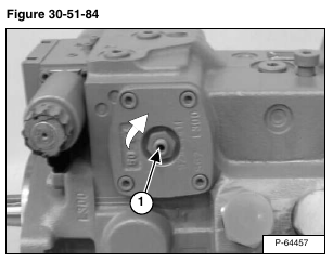
Turn the adjustment screw (Item 1) [Figure 30-51-84] clockwise, until one of the gauges registers an increase in system pressure. Mark the position of the adjustment screw.
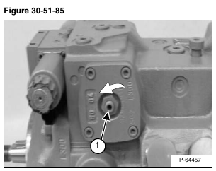
Turn the adjustment screw (Item 1) [Figure 30-51-85] counterclockwise, until the other gauge registers an increase in system pressure. Mark the position of the adjustment screw.
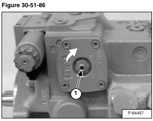
Turn the adjustment screw (Item 1) [Figure 30-51-86] clockwise, to a position halfway between the recorded positions. The pressure gauges should read equal pressures.
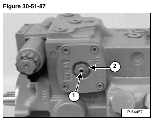
While holding the adjustment screw (Item 1) in position, tighten the lock nut (Item 2) [Figure 30-51-87] to 22 ft.-lb. (30 N•m) torque.
Shut loader OFF.
Remove the hydraulic hose from the X1 and X2 ports on the pump. Install the plugs and tighten to 18 ft.-lb. (25 N•m) torque.
Remove the pressure gauges from the MA and MB ports on the pump. Install the plugs and tighten to 18 ft.-lb. (25 N•m) torque.
NOTE: The Hydraulic Controller Neutral Adjustment must be performed whenever the Mechanical Neutral Adjustment is done. (See Hydraulic Controller Neutral Adjustment on Page 30-41-28.)
