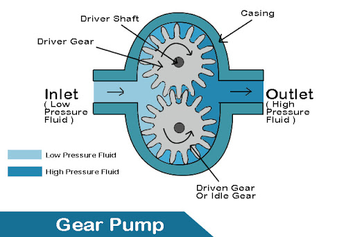
A gear pump is a type of positive displacement pump that uses the meshing of gears to move fluid by displacement. It is commonly used for hydraulic power applications and for pumping high-viscosity fluids such as oil. In this article, we will explain the main parts of a gear pump and how it works.
Parts of a Gear Pump
A gear pump consists of the following main parts:
- Prime mover: This is the source of mechanical power that drives the pump. It can be an electric motor, an internal combustion engine, or a manual crank.
- Driver gear: This is the gear that is connected to the prime mover and rotates the driven gear. It is also called the power gear or the master gear.
- Driven gear: This is the gear that meshes with the driver gear and rotates in the opposite direction. It is also called the idle gear or the slave gear.
- Housing: This is the casing that encloses the gears and forms the suction and discharge ports of the pump.
- Inlet port: This is the opening in the housing where the fluid enters the pump from the suction side. It is also called the suction port or the suction side.
- Outlet port: This is the opening in the housing where the pressurized fluid exits the pump to the discharge side. It is also called the discharge port or the discharge side.
- Pressure relief valve: This is a safety device that prevents the pump from being damaged by excessive pressure. It opens when the pressure in the discharge side exceeds a certain limit and allows some fluid to flow back to the suction side or to a reservoir.
- Seal: This is a device that prevents the leakage of fluid from the pump and the entry of air or contaminants. It can be a mechanical seal, a lip seal, or a packing seal.
The following table summarizes the parts of a gear pump and their functions:
| Part | Function |
|---|---|
| Prime mover | Provides mechanical power to the pump |
| Driver gear | Rotates the driven gear |
| Driven gear | Meshes with the driver gear and moves the fluid |
| Housing | Encloses the gears and forms the ports |
| Inlet port | Allows the fluid to enter the pump |
| Outlet port | Allows the pressurized fluid to exit the pump |
| Pressure relief valve | Protects the pump from excessive pressure |
| Seal | Prevents leakage and contamination |
How a Gear Pump Works
The working principle of a gear pump is based on the displacement of fluid by the meshing of gears. As the gears rotate, they create a vacuum on the inlet side of the pump, which draws the fluid into the pump. The fluid is then trapped between the teeth of the gears and the housing and carried to the outlet side of the pump, where the meshing of the gears forces the fluid out of the pump. The flow rate of the pump is proportional to the rotational speed of the gears and the size of the gear teeth. The pressure of the pump depends on the resistance of the system and the clearance between the gears and the housing.
The following diagram illustrates the working of a gear pump:
The advantages of a gear pump are:
- It can handle high-viscosity fluids and deliver a smooth and pulse-free flow.
- It can operate at high pressures and speeds with good efficiency and reliability.
- It has a simple and compact design and requires low maintenance.
The disadvantages of a gear pump are:
- It is sensitive to wear and tear due to the contact between the gears and the housing.
- It is prone to cavitation and noise due to the rapid change of pressure and velocity in the pump.
- It cannot handle abrasive or corrosive fluids or fluids with solid particles.
