Remove the hydrostatic pump/engine assembly from the loader. (See Engine Removal And Installation on Page 70-10-8.)
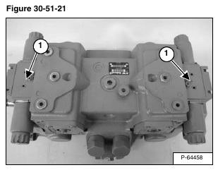
Remove the hydraulic controllers (Item 1) [Figure 30-51-21]. (See Hydraulic Controller Removal And Installation on Page 30-41-2.)
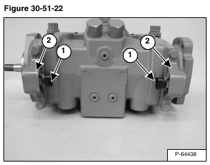
Swash plate angle sensors (Item 1) are mounted on the bottom of the hydrostatic pump. They are protected by steel covers (Item 2) [Figure 30-51-22].
Note the connectors facing each other.
Note the steel covers facing direction.
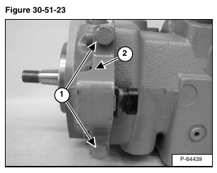
Remove the bolts (Item 1) mounting the steel covers (Item 2) [Figure 30-51-23].
Assembly: Tighten bolts to 38 ft.-lb. (51 N•m) torque.
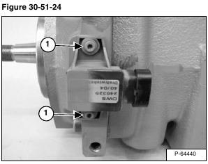
Remove the mounting bolts and washers for the swash plate angle sensor (Item 1) [Figure 30-51-24].
Assembly: Tighten bolts to 27.4 in.-lb. (3,1 N•m) torque.
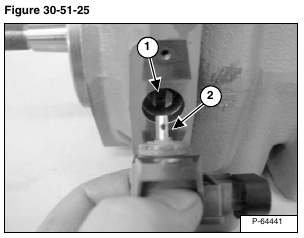
Assembly: Note the slotted portion (Item 1) of the positioning pin tightly fits the machined section on the swash plate angle sensor shaft (Item 2) [Figure 30-51-25].
Note the machined section of the swash plate angle sensor shaft faces the center of the hydrostatic pump.
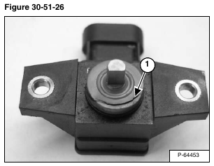
NOTE: Improperly installing the swash plate angle sensor, with the shaft facing toward the outside of the hydrostatic pump, will make it hard to install the sensor mounting bolts and also destroy the seal (Item 1) [Figure 30-51-26].
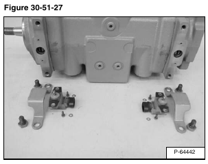
Both swash plate angle sensors and associated hardware removed from the hydrostatic pump. [Figure 30-51-27].
Right End Housing
Left End Housing
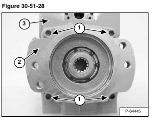
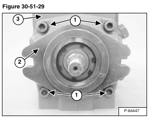
Remove the four mount bolts (Item 1) securing the end housing (Item 2) to the main case housing (Item 3) [Figure 30-51-28] and [Figure 30-51-29].
Assembly: Alternately, tighten mount bolts to 96 ft.-lb. (130 N•m) torque.
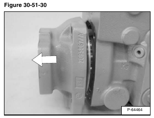
Pull the end housings from the case housing [Figure 30-51-30].
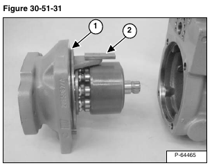
Replace O-ring (Item 1) [Figure 30-51-31].
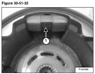
Ensure servo follower (Item 2) [Figure 30-51-31] is swung out for proper engagement with the notch in the servo piston (Item 1) [Figure 30-51-32].
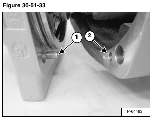
Assembly: Ensure dowel pin (Item 1) is aligned with hole in case housing (Item 2) [Figure 30-51-33] before tightening screws.
Remove valve plate (Item 1) [Figure 30-51-34] and [Figure 30-51-35] from the case housing.
Inspect valve plate for scratches or scoring. Replace a valve plate if the scratches are deep enough to catch with a fingernail.
NOTE: Pay attention to the notches (Item 2) [Figure 30-51-34] and [Figure 30-51-35] in the valve plate for assembly reasons. There are different valve plates for the left and right side. The valve plates are NOT interchangeable.
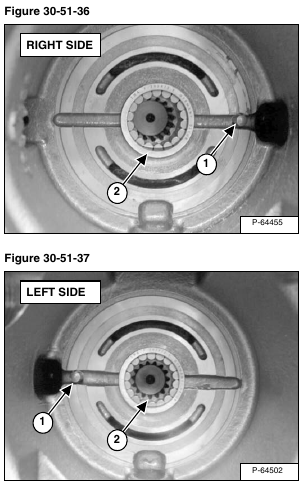
Assembly: Align the timing pin (Item 1) [Figure 30-51-36] and [Figure 30-51-37] in the case housing with the notch (Item 1) [Figure 30-51-38] and [Figure 30-51-39] that does not go through the valve plate.
Align the shoulder of the roller bearing (Item 2) [Figure 30-51-36] and [Figure 30-51-37] with the beveled edge on the valve plate (Item 2) [Figure 30-51-38] and [Figure 30-51-39].
NOTE: Valve plate should sit FLUSH with the case housing when properly installed.
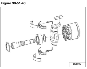
Right Side Rotating Group [Figure 30-51-40].
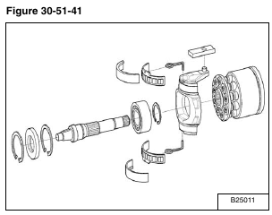
Left Side Rotating Group [Figure 30-51-41].
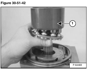
Remove the piston assembly (Item 1) [Figure 30-51-42].
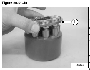
Remove the pistons (Item 1) [Figure 30-51-43] from the rotating block.
Inspect the pistons, look for scoring and scratches.
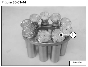
Ensure the holes (Item 1) [Figure 30-51-44] in the slippers, are not plugged.
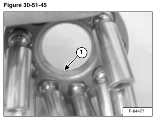
Inspect the mating surface of the spherical washer for scoring or scratches (Item 1) [Figure 30-51-45].
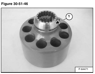
Remove the spherical washer (Item 1) [Figure 30-51-46].
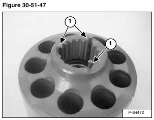
Inspect the pins (Item 1) [Figure 30-51-47]. They should be all the same length. Do not remove.
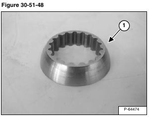
Inspect the spherical washer for scoring and wear (Item 1) [Figure 30-51-48].
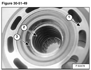
Inspect the back surface of the rotating block (Item 1) [Figure 30-51-49] where the valve plate seals. Ensure there is no scratches or scoring.
Visually ensure spring (Item 2) and c-clip (Item 3) [Figure 30-51-49] are not bent or damaged.
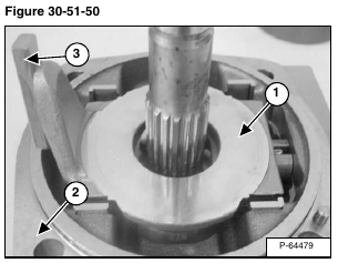
Inspect mating surface for the slippers on the swash plate (Item 1) [Figure 30-51-50].
Remove the swash plate from the endcap housing (Item 2) [Figure 30-51-50].
Remove the slide ring (Item 3) [Figure 30-51-50], ensure it pivots freely.
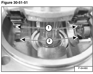
Assembly: Carefully align bearing pin eyelets (Item 1) into holes in endcap housing (Item 2) [Figure 30-51-51].
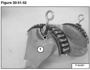
Assembly: Ensure bearing pins are in the holes of the swash plate (Item 1) [Figure 30-51-52].
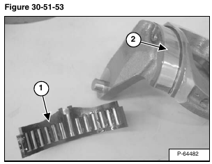
Remove the shell bearing (Item 1) [Figure 30-51-53].
Inspect individual roller bearings and machined surfaces (Item 2) [Figure 30-51-53] on swash plate.
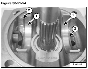
Remove the shell bearing races (Item 1) [Figure 30-51-54].
Assembly: Note shell bearing races have an edge (Item 2) [Figure 30-51-54] on them. The edges face towards the outside of the endcap housing
Inspect bearing surfaces for scratches or scoring.
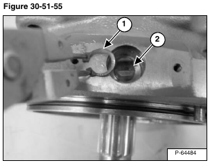
Remove the snap ring (Item 1) from the positioning pin (Item 2) [Figure 30-51-55].
Pull the positioning pin from the end housing.
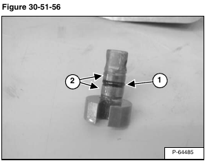
Replace O-ring (Item 1) [Figure 30-51-56].
Inspect wear surfaces (Item 2) [Figure 30-51-56] for scratches or scoring. Ensure positioning pin can rotate smoothly in the end housing without excessive play.
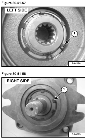
Remove the snap ring (Item 1) [Figure 30-51-57] and [Figure 30-51-58] from the end housing.
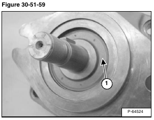
The pump seal (Item 1) [Figure 30-51-59] is removed by inserting a screw into the seal and prying out.
The drive shaft can be tapped out of the end housing with a rubber mallet.
Inspect wear surfaces for scratches, and inspect splines for excessive wear.
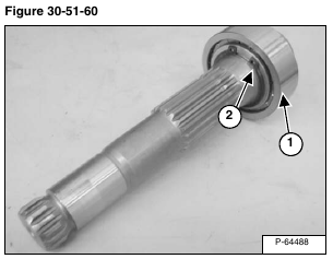
Inspect bearing (Item 1); if bearing needs replacement, remove snap ring (Item 2) [Figure 30-51-60] and remove bearing.
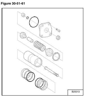
Servo Piston Assembly [Figure 30-51-61].
The Servo Piston Assembly [Figure 30-51-61] cannot be removed unless the hydraulic controller and rotating group is removed first.
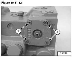
Remove servo piston mounting bolts (Item 1) [Figure 30-51-62].
Installation: Tighten bolts to 7.7 ft.-lb. (10,4 N•m) torque.
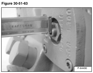
Measure and record servo piston depth at the adjustment screw [Figure 30-51-63].
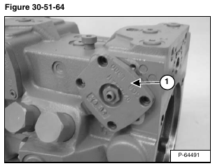
Use a rubber mallet to rotate servo piston cover (Item 1) [Figure 30-51-64].
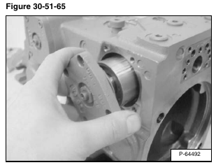
Slide the servo piston assembly out of the bore. [Figure 30-51-65].
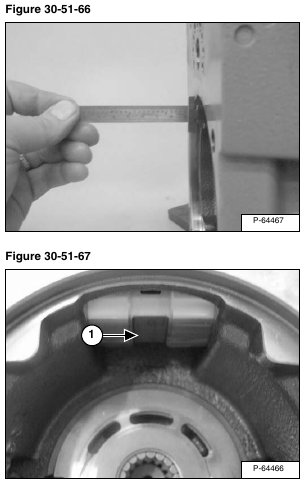
Assembly: Align the servo piston so the guide slot (Item 1) [Figure 30-51-67] is parallel to the driveshaft centerline. Measure with a straight-edge [Figure 30-51-66].
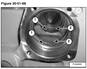
Remove the bushings (Item 1), seals and O-rings (Item 2) [Figure 30-51-68] from the pump housing.
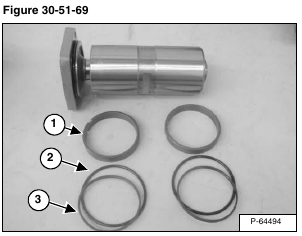
Each servo has a pair of bushings (Item 1), O-rings (Item 2) and square-cut seals (Item 3) [Figure 30-51-69].
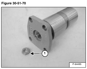
Remove the lock nut (Item 1) [Figure 30-51-70] from the servo piston.
Assembly: Tighten lock nut to 22 ft.-lb. (30 N•m) torque.
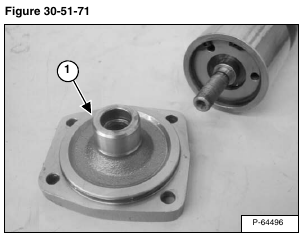
Remove the servo cover (Item 1) [Figure 30-51-71] from the servo piston.
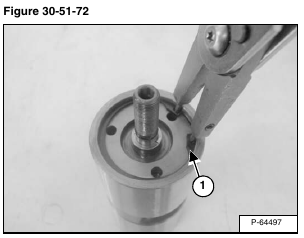
Remove snap ring (Item 1) [Figure 30-51-72] from the servo piston.
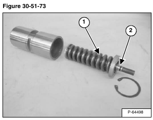
Remove the piston stop adjustment mechanism (Item 1) [Figure 30-51-73] from the servo piston.
Inspect mechanism for broken parts.
Replace O-ring (Item 2) [Figure 30-51-73]
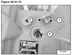
Remove the plug (Item 1) from the top center of the case housing. Replace O-ring (Item 2) [Figure 30-51-74].
Assembly: Tighten plug to 45 ft.-lb. (10 N•m) torque.
Remove internal screen (Item 3) [Figure 30-51-74].
Assembly: Tighten internal screen to 7.4 ft.-lb. (62 N•m) torque.
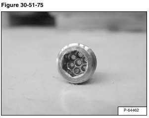
Ensure screen is clean [Figure 30-51-75].
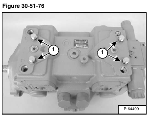
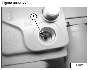
Remove the four control pressure plugs (Item 1) [Figure 30-51-76] at the top of the case housing to gain access to the four orifices (Item 1) [Figure 30-51-77].
Replace O-rings on plugs.
Assembly: Tighten plugs to 18 ft.-lb. (25 N•m) torque.
Ensure the four orifices (Item 1) [Figure 30-51-77] in case housing are clean and not plugged.
NOTE: The four orifices are no longer needed when software version 69 or above is installed on the loader.
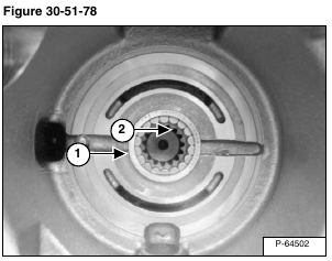
Bearings (Item 1) [Figure 30-51-78] in case housing are replaced by using a press and bearing driver.
Inspect center coupler (Item 2) [Figure 30-51-78].
