The hydraulic controller neutral adjustment, aligns the pump swash plate and the control spool so that a zero angle control setting provides a zero degree swash plate setting. This adjustment should be performed whenever any part of the control or swash plate mechanisms are adjusted or removed or after the pump mechanical neutral setting is adjusted. Ensure the pump mechanical neutral setting is correct before performing hydraulic controller neutral adjustments.
NOTE: Procedure is shown for the left side hydraulic controller. Procedure is the same for the right side hydraulic controller, except you disconnect the electrical connectors for the right side hydraulic controller and connect pressure gauges in the X1 and X2 ports on the right side of the pump.
Place the loader on jack stands. (See Procedure on Page 10-10-1.)
Raise the lift arms, and install an approved lift arm support device. (See Installing on Page 10-20-1.)
Raise the operator cab. (See Raising on Page 10-30-2.)
Connect the remote start tool. (See REMOTE START TOOL KIT-MEL1563 on Page 10-60-1.)
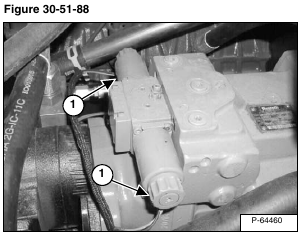
Disconnect the hydraulic controller connectors (Item 1) [Figure 30-51-88] from the loader wiring harness for the hydraulic controller you are adjusting.
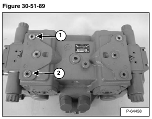
Remove the X1 plug (Item 1) and X2 plug (Item 2) [Figure 30-51-89] pertaining to the side of the hydrostatic pump you are adjusting.
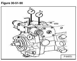
Install 500 PSI pressure gauges in the X1 and X2 ports pertaining to the side of the hydrostatic pump you are adjusting.
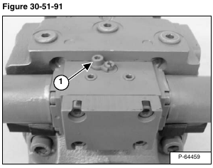
Loosen the locking screw (Item 1) [Figure 30-51-91].
Start the loader using the remote start tool and run at an idle.
Turn the adjustment screw (Item 1) [Figure 30-51-92] clockwise, until one of the gauges registers an increase in system pressure. Mark the position of the adjustment screw.
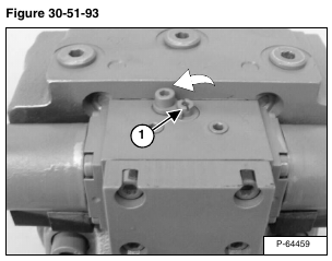
Turn the adjustment screw (Item 1) [Figure 30-51-93] counterclockwise, until the other gauge registers an increase in system pressure. Mark the position of the adjustment screw.
Turn the adjustment screw (Item 1) [Figure 30-51-94] clockwise, to a position halfway between the recorded positions. The pressure gauges should read equal pressures.
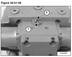
While holding the adjustment screw (Item 1) in position, tighten the locking screw (Item 2) [Figure 30-51-95] to 4.5 ft.-lb. (6,1 N•m) torque.
Shut loader OFF.
Remove the pressure gauges from the X1 and X2 ports on the pump. Install the plugs and tighten to 18 ft.-lb. (25 N•m) torque.
Connect the hydraulic controller wire connectors to the loader wiring harness.
Perform a controller calibration procedure.
(See CALIBRATION on Page 60-160-1.)
