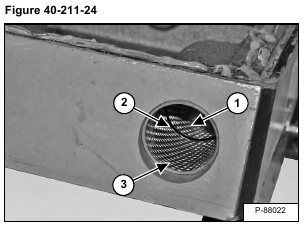
Install bushing (Item 1), O-ring (Item 2) and bushing (Item 3) [Figure 40-211-24] in both locking pin bores.
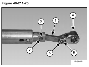
Install reversing lever (Item 1), pin (Item 2) and snap ring (Item 3) [Figure 40-211-25] on the locking pin.
Install the driving fork (Item 4), pin (Item 5) and snap ring (Item 6) [Figure 40-211-25] on the reversing lever.
Repeat the procedure for the other locking pin.
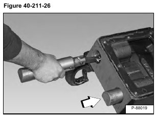
Install the locking pin assemblies [Figure 40-211-26].
NOTE: Position the locking levers with the flat side down and away from the cover.
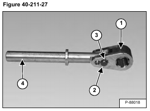
Install the driving fork (Item 1), pin (Item 2) and snap ring (Item 3) on the spring guide (Item 4) [Figure 40-211-27].
Install the O-rings (Item 1) [Figure 40-211-28].
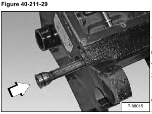
Install the control shaft [Figure 40-211-29].
Install the control shaft through the first locking lever driving fork (Item 1) [Figure 40-211-30].
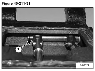
Install the control shaft through the spring guide driving fork (Item 1) [Figure 40-211-31].
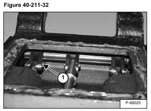
Install the control shaft through the second locking lever driving fork (Item 1) [Figure 40-211-32].
NOTE: Check proper alignment of all three driving forks on the control shaft. If not aligned properly, repeat the procedure.
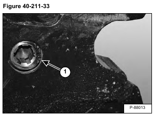
Install the snap ring (Item 1) [Figure 40-211-33].
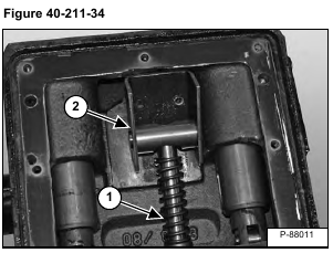
Install pressure spring (Item 1) on the spring guide. Tilt the bearing block and pivoting journal (Item 2) [Figure 40-211-34] down and install on the spring guide.
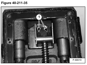
Install the two bolts (Item 1) [Figure 40-211-35].
Apply a bead of sealant around the cover mounting surface (Item 1) [Figure 40-211-36].
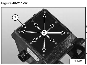
Install the cover (Item 1) [Figure 40-211-37].
Apply Loctite® 242 on the eight bolts.
Install the eight bolts (Item 2) [Figure 40-211-37].
