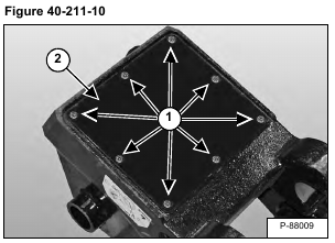
Remove the eight bolts (Item 1) and cover (Item 2) [Figure 40-211-10].
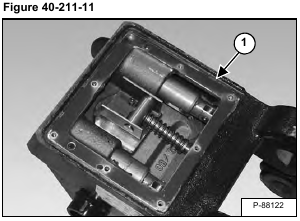
Remove all sealant (Item 1) [Figure 40-211-11] from the housing and cover.
NOTE: Do not scratch the mounting surface while removing sealant.
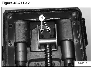
Remove the two bolts (Item 1) [Figure 40-211-12].
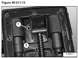
Tilt the bearing block and pivoting journal (Item 1) up and remove from the spring guide (Item 2) [Figure 40-211-13].
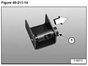
Remove the pivoting journal (Item 1) [Figure 40-211-14] from the bearing block.
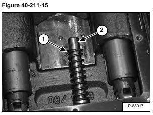
Remove the pressure spring (Item 1) from the spring guide (Item 2) [Figure 40-211-15].
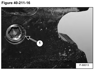
Remove the snap ring (Item 1) [Figure 40-211-16].
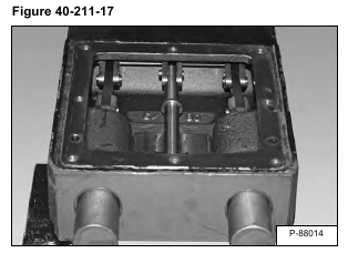
NOTE: Before removing the control shaft, note the position of each of the components so that when the coupler is reassembled all components are positioned correctly on the control shaft [Figure 40-211-17].
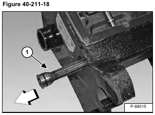
Remove the control shaft (Item 1) [Figure 40-211-18].
Remove O-rings (Item 1) [Figure 40-211-19].
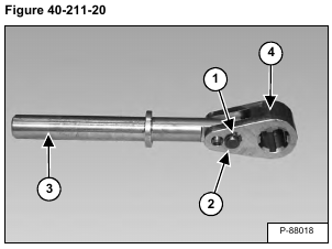
Remove the snap ring (Item 1) and pin (Item 2). Remove the spring guide (Item 3) from the driving fork (Item 4) [Figure 40-211-20].
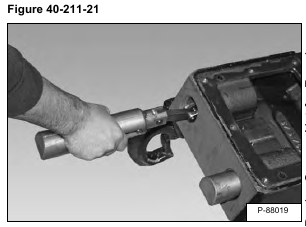
Remove the locking pin assemblies [Figure 40-211-21].
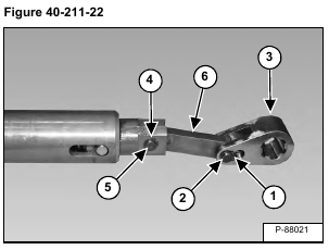
Remove the snap ring (Item 1) and pin (Item 2). Remove the driving fork (Item 3) [Figure 40-211-22].
Remove the snap ring (Item 4) and pin (Item 5). Remove the reversing lever (Item 6) [Figure 40-211-22].
Repeat the procedure for the other locking pin.
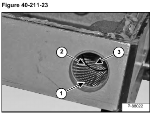
Remove the bushing (Item 1), O-ring (Item 2) and bushing (Item 3) [Figure 40-211-23] from both locking pin bores.
