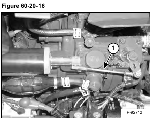
Pry down on the linkage (Item 1) [Figure 60-20-16] and remove the linkage from the actuator.
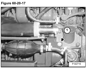
Remove the bolt (Item 1) [Figure 60-20-17].
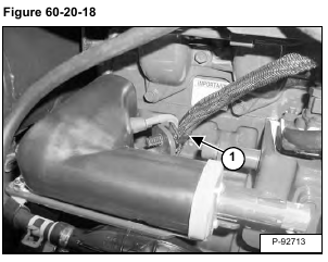
Cut and remove the cable tie (Item 1) [Figure 60-20-18].
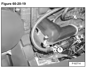
Remove the bolt (Item 1) [Figure 60-20-19] and reposition the fuel line.
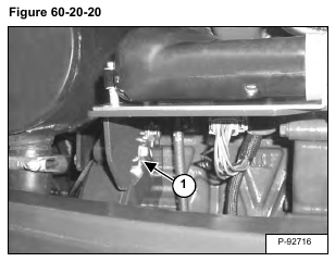
Remove the bolt (Item 1) [Figure 60-20-20].
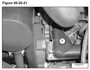
Remove the bolt (Item 1) [Figure 60-20-21].
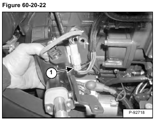
Tip the actuator / mount assembly over and disconnect the wire harness (Item 1) [Figure 60-20-22].
Remove the actuator / mount assembly from the excavator.
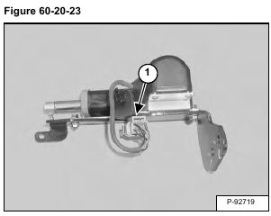
Install a flat bladed screw driver in the slot (Item 1) [Figure 60-20-23] of the wire harness connector.
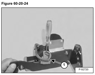
Push down on the screw driver to remove the connector (Item 1) [Figure 60-20-24] from the mount.
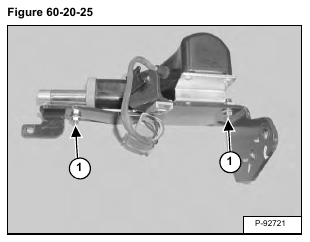
Remove the two bolts and nuts (Item 1) [Figure 60-20-25]. Remove the actuator from the mount.
After installing the actuator, the engine speed control system must be calibrated. (See Calibration on Page 60-20-3.)
