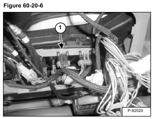
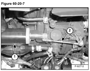
The engine speed control components must be calibrated any time the controller (Item 1) [Figure 60-20-6] and or the actuator (Item 1) [Figure 60-20-7] has been replaced or if the linkage (Item 2) [Figure 60-20-7] has been adjusted.
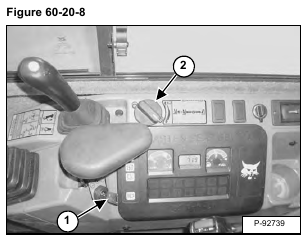
With the engine off, turn the key (Item 1) to the ON position. Rotate the engine speed control dial (Item 2) [Figure 60-20-8] to the high speed position.
Leave the engine speed control dial at the high speed position and turn the key to the STOP position.
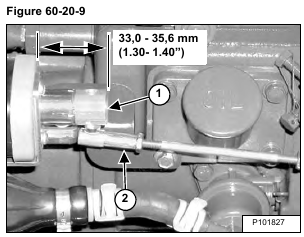
Measure from the face of the seal to the end of the actuator plunger. The plunger (Item 1) [Figure 60-20-9] must be between 33,0 – 35,6 mm (1.30 – 1.40 in).
If the actuator plunger needs to be adjusted, push down and disconnect the linkage (Item 2) [Figure 60-20-9].
Manually pull or push the actuator plunger (Item 1) [Figure 60-20-9] to a point between 33,0 – 35,6 mm (1.30- 1.40 in). This is the actuator starting point for the calibration procedure.
If the actuator is less than specified a E0522 error code, out of range low, will be generated. If the actuator is greater than specified, a E0521 error code, out of range high, will be generated.
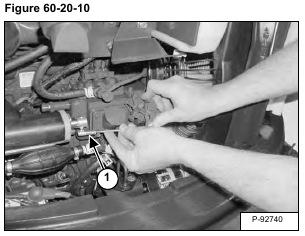
Connect the linkage (Item 1) [Figure 60-20-10] to the actuator.
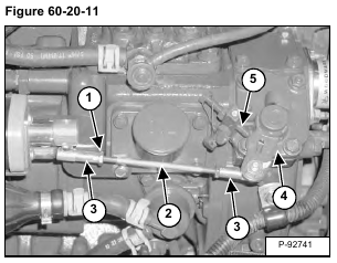
Loosen the nuts (Item 1). Push down and disconnect the linkage (Item 2). Turn the ball joints (Item 3) a small amount and reconnect the linkage. Repeat the procedure until the lever (Item 4) fully contacts the stop (Item 5) [Figure 60-20-11].
Tighten the nuts (Item 1) [Figure 60-20-11].
The following procedure must be completed within 7.5 seconds;
With the engine off and the engine speed control dial at the high speed position, turn the key to the ON position.
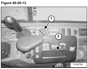
Turn the engine speed control dial (Item 1) [Figure 60-20-12] from the high speed position to the low speed position four times:
High Speed
Low Speed
High Speed
Low Speed
High Speed
Low Speed
High Speed
Low Speed
NOTE: The auto idle icon (Item 2) [Figure 60-20-12] will flash while the calibration procedure is in process.
NOTE: The calibration procedure may start after the third rotation of the speed control dial.
When the calibration procedure is complete, the operator warning alarm will sound twice. Turn the key to the STOP position.
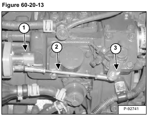
NOTE: The actuator plunger (Item 1), linkage (Item 2) and lever (Item 3) [Figure 60-20-13] will move several times during the calibration procedure. Keep all personnel, tools and shop towels away from all moving components while performing the calibration procedure
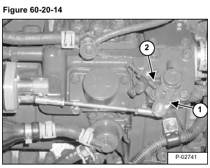
After the calibration procedure has been completed, with the engine off, turn the key to the ON position. Turn the engine speed control to the high speed position. The engine speed control lever (Item 1) must contact the stop (Item 2) [Figure 60-20-14].
Turn the engine speed control to the low speed position.
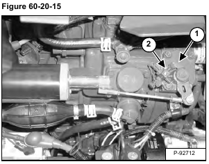
The engine speed control lever (Item 1) must contact the stop (Item 2) [Figure 60-20-15].
If the control lever does not contact both stops, repeat the calibration procedure.
