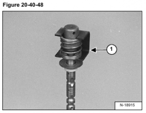
Put the linkage end of the spool assembly [Figure 20-40-48] in a vise.
Install MEL1285 Spring Compressor Tool (Item 1) [Figure 20-40-48] on the spring assembly.
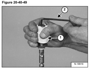
Put a rag around the detent assembly (Item 1) [Figure 20-40-49] to prevent losing the two detent balls when the detent adapter is removed.
NOTE: Be careful when removing the detent adapter from the centering spring, the spring is under
pressure.
Use an allen wrench (Item 2) [Figure 20-40-49] to remove the detent adapter.
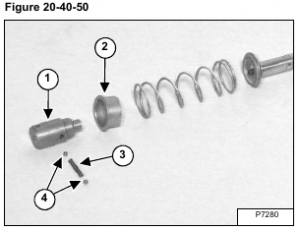
Remove the detent adapter (Item 1) from the adapter retainer (Item 2) [Figure 20-40-50].
Remove the detent spring (Item 3) and detent balls (Item 4) [Figure 20-40-50].
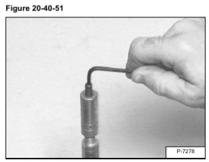
Lift Spool Only: Remove the stud from the end of the spool [Figure 20-40-51].
Removal of plastic plug.
• Make a center point in the plug using a 3/16 inch drill.
• Drill a hole all the way through the plug using a 7/64 inch tap drill.
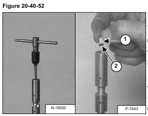
• Turn a 6-62 tap into the plug [Figure 20-40-52]. Pull the tap and plug out of the spool. BE CAREFUL, do not break the tap.
• Clean all the debris from the inside of the spool bore.
Assembly: Install the new plastic plug (Item 1) and O- ring (Item 2) [Figure 20-40-52].
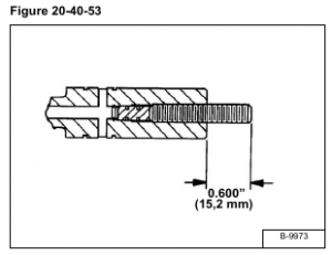
Install the stud and leave 0.600 inch (15,2 mm) past the end of the spool [Figure 20-40-53].
NOTE: DO NOT US LOCTITE ON THE STUD THREADS. DO NOT EXCEED 70 in.-lb. (8 N•m) torque during stud installation. Excess torque may cause spool distortion resulting in sticky spool operation.
NOTE: Put grease on all detent component surfaces before assembly.
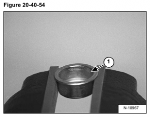
Install the collar (Item 1) [Figure 20-40-54] in a vise. DO NOT overtighten the vise.
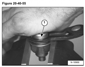
Install the detent balls and spring into the detent adapter (Item 1). Hold the detent balls in position with the tool and install the detent adapter into the end cap [Figure 20-40-55].
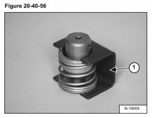
Install the MEL 1285 Compression Spring Tool (Item 1) [Figure 20-40-56] over the washer, spring, collar, and detent adapter.
NOTE: Be careful when installing the assembly in the spring tool, the assembly is under spring pressure.
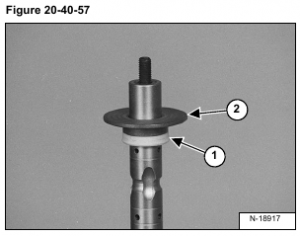
Install the spool seal (Item 1) and back-up washer (Item 2) [Figure 20-40-57] on the spool.
NOTE: The larger diameter of the seal surface must be installed toward the inside of the control valve.
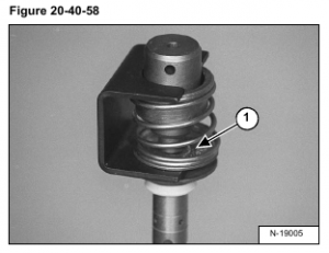
Install the spring assembly on the lift spool hand tight [Figure 20-40-58].
Remove the spring tool. Check the alignment of the detent adapter and the washer.
NOTE: The adapter must fit in the center of the washer (Item 1) [Figure 20-40-58].
Tighten the detent adapter to 90-100 in.-lb. (10,2-11,3 N•m) torque.
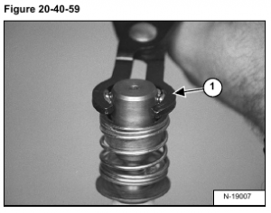
Install the detent balls and spring in the adapter. Hold the detent balls in place with the detent pliers (Item 1) [Figure 20-40-59].
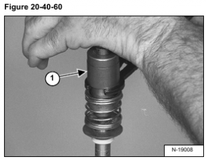
Install the detent sleeve (Item 1) [Figure 20-40-60] on the detent adapter.
While holding the detent balls in position with the tool, push the detent adapter into the end cap [Figure 20-40-60]