Raise the loader operator cab. (See Raising on Page 10-30-2.)
NOTE: The loader control panel and linkage crossbar have been removed for clarity purpose only. The traction lock can be removed without removing the control panel.
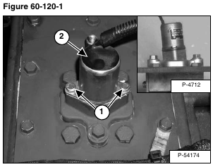
Remove the two mounting screws (Item 1) [Figure 60-120-1] from the electric solenoid mounting bracket.
Installation: Tighten the mounting screws to 80 – 90 in.-lb. (9 – 10 N•m) torque.
Remove the electric solenoid (Item 2) from the chaincase cover [Figure 60-120-1].
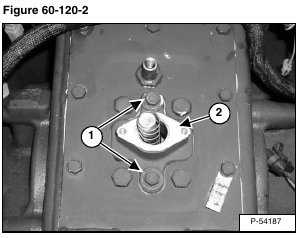
Remove the two bolts (Item 1) and remove the bracket (Item 2) [Figure 60-120-2] from the chaincase cover.
Installation: Apply polyurethane sealer to the bolt threads and tighten the mounting bolts to 25 – 28 ft.-lb. (34 – 38 N•m) torque.
Be sure the solenoid mounting bracket is installed in the same position. The solenoid mounting surface has a slight angle which tips the top of the solenoid toward the rear of the loader when installed correctly. See inset photo [Figure 60-120-1].
Remove the traction lock assembly (Item 1) [Figure 60-120-3] from the chaincase.
Inspect gasket (Item 2) [Figure 60-120-3], replace if necessary.
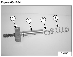
Remove and inspect the compression spring (Item 1) and spring cap washer (Item 2) [Figure 60-120-4] for wear or damage. Replace if necessary. The spring may also stay with the shaft when the electric solenoid and bracket are removed from the chaincase.
Installation: Install the compression spring (Item 1) [Figure 60-120-4] on the collar located on the electric solenoid.
Inspect the shaft (Item 3) and wedge (Item 4) [Figure 60-120-4] for scoring and deep scratches, replace if damaged. (Item 3) [Figure 60-120-4] from the chaincase.
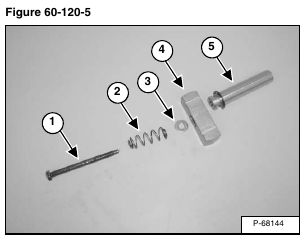
Remove the shaft mounting bolt (Item 1), spring (Item 2), washer (Item 3) and wedge (Item 4) from the assembly shaft (Item 5) [Figure 60-120-5]. Inspect all parts for damage or wear. Replace if necessary.
Installation: Thoroughly clean and dry the shaft mounting bolt (Item 1), the shaft (Item 5) and wedge (Item 4) [Figure 60-120-5]. Use Loctite® #242 when assembling these parts to the traction lock assembly.
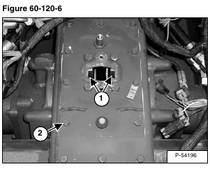
Inspect the guides (Item 1) [Figure 60-120-6] for wear or damage. Replace if necessary.
If replacement is necessary, remove the center chaincase cover. Remove the screws (Item 2) [Figure 60-120-6] and pry the center cover off.
Installation: Apply polyurethane sealant to the screw threads and center chaincase cover. Tighten screws to 15 – 20 ft.-lb. (20 – 27 N•m) torque.
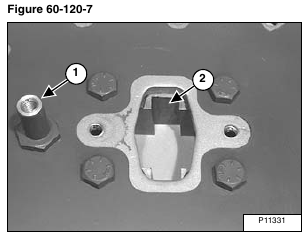
NOTE: Bolt (Item 1) is on the rear of the chaincase cover, notice the direction of the groove (Item 2) [Figure 60-120-7] in the traction lock guides.
To remove the traction lock guides remove the four bolts (Item 1) [Figure 60-120-8].
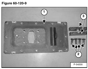
Installation: Thoroughly clean the polyurethane from the chaincase cover (Item 1), bolts (Item 2) and traction lock guides (Item 3) [Figure 60-120-9] and dry.
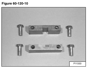
Installation: Apply a bead of polyurethane on the traction lock guides and bolts [Figure 60-120-10].
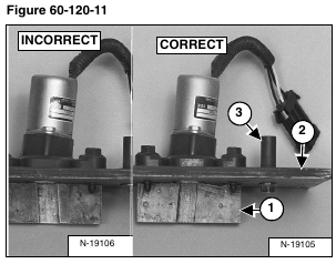
Install the traction lock guides (Item 1) to the chaincase cover (Item 2) [Figure 60-120-11] using the four bolts (removed earlier).
Do not tighten at this time.
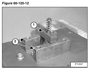
Install the traction wedge assembly (Item 1) into the solenoid and traction lock guides (Item 2) [Figure 60-120-12].
After the bolts have been tightened recheck to make sure the shaft assembly is moving freely in the guides.
Remove the wedge assembly (Item 1) [Figure 60-120-12].
NOTE: The wedge assembly must slide freely in the grooves of the guides. Tighten the four guide bolts to 90 – 100 ft.-lb. (123 – 135 N•m) torque.
Lower operator cab. (See Raising on Page 10-30-2.)
Perform the BICS inspection procedure. (See Inspecting The BICS Controller (Engine STOPPED – Key ON) on Page 60-100-2.)
