The tools listed will be needed to do the following procedure:
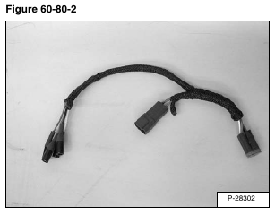
MEL1609-Wheel Speed Sensor Test Harness
[Figure 60-80-2]
MEL1563 or 6689779-Remote Start Tool
Multimeter
Raise the lift arms and install an approved lift arm support device. (See Installing on Page 10-20-1.)
Raise the operator cab. (See Raising on Page 10-30-2.)
Connect the remote start tool to the loader. (See REMOTE START TOOL KIT-MEL1563 on Page 10-60-1.)
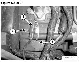
Locate the speed sensor (Item 1) [Figure 60-80-3] on the top of the right or left hydrostatic motor carrier.
Remove the transmission cover screw (Item 2) [Figure 60-80-3], to loosen the connector clamp.
Installation: Tighten screw to 15 – 20 ft.-lb. (20 – 27 N•m) torque.
Disconnect the speed sensor wire connector (Item 3) [Figure 60-80-3] from the loader harness wire connector.
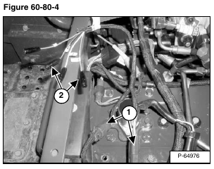
Connect the speed sensor test harness (Item 1) [Figure 60-80-4] in line, between the loader wiring harness and the speed sensor harness.
Turn the remote start key to ON position without starting the loader.
Take a voltage reading, with the multimeter, at the speed sensor test harness, between pin 1 and pin 3 (Item 2) [Figure 60-80-4].
The voltage should be approximately 5 volts.
Repeat the procedure for the opposite side speed sensor. (If needed.)


