Raise the lift arms and install an approved lift arm support device. (See Installing on Page 10-20-1.)
Raise the operator cab. (See Raising on Page 10-30-2.)
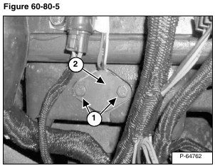
Remove the two, speed sensor mount bolts (Item 1) [Figure 60-80-5] from the top of the hydrostatic motor carrier.
Remove the mount plate (Item 2) [Figure 60-80-5].
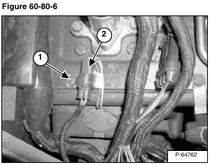
Remove the transmission cover screw (Item 1) [Figure 60-80-6], to loosen the connector clamp.
Installation: Tighten screw to 15 – 20 ft.-lb. (20 – 27 N•m) torque.
Disconnect the speed sensor electrical harness connector (Item 2) [Figure 60-80-6].
Lift the speed sensor (Item 1) [Figure 60-80-7] out from the motor carrier. DO NOT pull on the wires, gently pry up with a screwdriver if necessary.
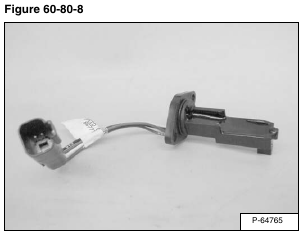
Remove the speed sensor [Figure 60-80-8].
The electrical connector can be replaced.
Remove the connector wedge (Item 1) [Figure 60-80-9].
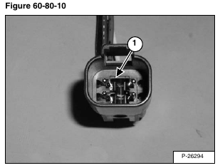
With a thin screwdriver lift the tabs and remove the wires from the connector (Item 1) [Figure 60-80-10].
Wire Code
1. Red
2. White
3. Black
4. Blue
Installation: Be sure to install the speed sensor (Item 1) [Figure 60-80-11] pointing toward the transmission case.
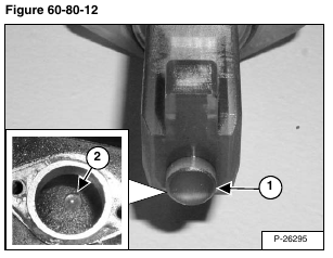
Installation: The alignment pin (Item 1) at the bottom of the speed sensor must be installed in the hole (Item 2) [Figure 60-80-12] in the motor carrier.
