Lift and block the loader. (See Procedure on Page 10-10-1.)
Raise the lift arm and install an approved lift arm support device. (See Installing on Page 10-20-1.)
Raise the operator cab. (See Raising on Page 10-30-2.)
Disconnect the negative battery cable. (See Removal And Installation on Page 60-20-1.)
Open the rear door.
Drain the hydraulic reservoir. (See Removing And Replacing Hydraulic Fluid on Page 10-120-2.)
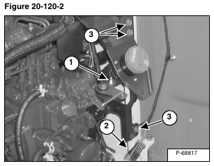
Remove the nut from the speed control linkage (Item 1) and unplug the rear lights electrical connector (Item 2) [Figure 20-120-2].
Remove the fuel fill bracket mounting screws (Item 3) [Figure 20-120-2]
Installation: Tighten screws to 15 – 20 ft.-lb. (20 – 27 N•m) torque.
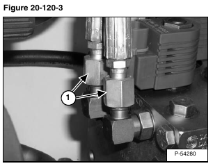
Remove the auxiliary coupler supply hoses (Item 1) [Figure 20-120-3] from the diverter block.
NOTE: Mark or tag all hoses and wires for proper orientation.
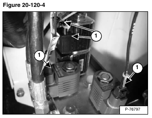
Disconnect the four solenoid connectors (Item 1) [Figure 20-120-4] from the rear auxiliary valve.
Disconnect the diverter valve outlet tubeline (Item 1) [Figure 20-120-5].
Remove the diverter valve supply hose (Item 1) [Figure 20-120-6].
Remove the diverter valve drain hose (Item 2) [Figure 20-120-6].
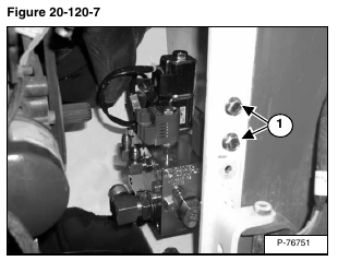
Remove the two mounting bolts (Item 1) [Figure 20-120-7].


