Clean the diverter valve to remove dirt before disassembly. Valve ports are labeled for correct assembly.
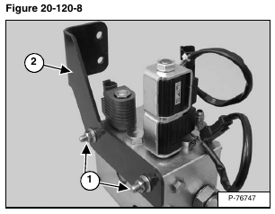
Remove the two mount bolts (Item 1) from the diverter valve mount plate (Item 2) [Figure 20-120-8] and remove the mount plate.
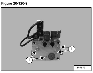
There are 11 #4 SAE hex head plugs (Item 1) [Figure 20-120-9] located on all sides of the diverter valve and can be removed for clean out purposes.
Assembly: Put oil on O-rings. Tighten to 10 ft.-lb. (13,6 N•m) torque.
Inspect O-ring (Item 1) [Figure 20-120-10].
Assembly: Put oil on O-ring.
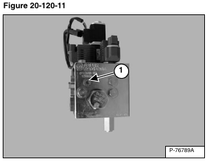
Remove the shuttle valve (Item 1) [Figure 20-120-11].
Assembly: Put oil on the O-rings and back-up washers.
Tighten to 8 ft.-lb. (10,8 N•m) torque.
Inspect the O-rings (Item 1) and back-up washers (Item 2) [Figure 20-120-12] for damage.
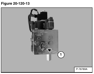
Remove the differential sensing valve (Item 1) [Figure 20-120-13].
Assembly: Put oil on O-rings and back-up washers.
Tighten to 85 ft.-lb. (115,25 N•m) torque.
Inspect the O-rings (Item 1) and back-up washers (Item 2) [Figure 20-120-14] for damage.
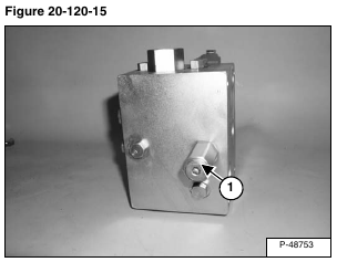
Remove the relief valve (Item 1) [Figure 20-120-15].
Assembly: Put oil on O-rings and back-up washers.
Tighten to 25 ft.-lb. (34 N•m) torque.
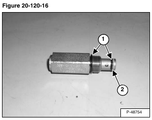
Inspect the O-rings (Item 1) and back-up washer (Item 2) [Figure 20-120-16] for damage.
NOTE: Before removing the solenoid coils, mark the coils for proper alignment.
Remove the nut (Item 1) [Figure 20-120-17] from the solenoid valve stem.
Assembly: Tighten the nut to 4 – 6 ft.-lb. (5 – 8 N•m) torque.
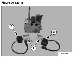
Remove the metal shields (Item 1) and solenoid valve coils (Item 2) [Figure 20-120-18].
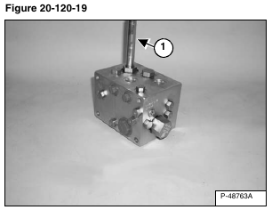
Remove the solenoid valve stem (Item 1) [Figure 20-120-19]
Assembly: Put oil on the O-rings and back-up washers.
Tighten to 25 ft.-lb. (34 N•m) torque.
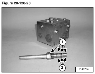
Inspect the O-rings (Item 1) and back-up washers (Item 2) [Figure 20-120-20] for damage.
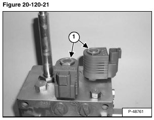
NOTE: Before removing the solenoid coils, mark the coils for proper alignment.
Remove the nuts (Item 1) [Figure 20-120-21] from the solenoid valve stems.
Assembly: Tighten the nut to 4 – 6 ft.-lb. (5 – 8 N•m) torque.
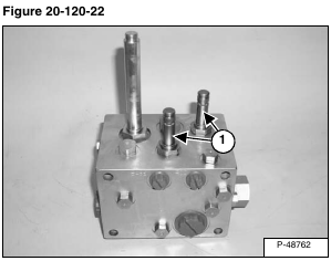
Remove the solenoid valve stems (Item 1) [Figure 20-120-22].
Assembly: Put oil on the O-rings and back-up washers.
Tighten to 25 ft.-lb. (34 N•m) torque.
Inspect the O-rings (Item 1) and back-up washer (Item 2) [Figure 20-120-23].
Remove the #8 SAE hex head plug (Item 1) [Figure 20-120-24].
Assembly: Tighten the plug to 38 ft.-lb. (51,5 N•m) torque.
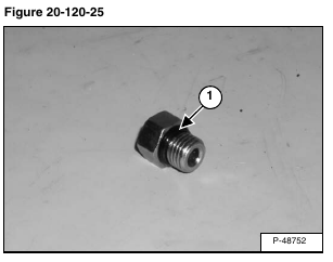
Inspect O-ring (Item 1) [Figure 20-120-25].
Assembly: Put oil on O-ring.
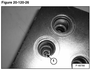
Remove and inspect the orifice (Item 1) [Figure 20-120-26] for dirt and debris.
Assembly: Tighten the orifice to 22 ft.-lb. (29,8 N•m) torque.
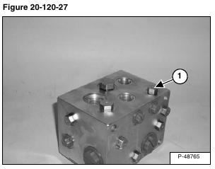
Remove the #4 SAE hex head plug (Item 1) [Figure 20-120-27].
Assembly: Tighten the plug to 10 ft.-lb. (13,6 N•m) torque.
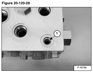
Remove the orifice (Item 1) [Figure 20-120-28] and inspect for dirt and debris.
Assembly: Tighten the orifice to 3.3 ft.-lb. (4,5 N•m) torque.
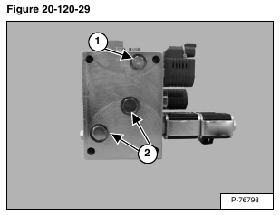
Remove the #4 SAE hex head plug (Item 1) and the #6 SAE hex head plugs (Item 2) [Figure 20-120-29].
Assembly: Tighten the #4 SAE hex head plug to 10 ft.- lb. (13,6 N•m) torque.
Assembly: Tighten the #6 SAE hex head plugs to 14 ft.- lb. (19 N•m) torque.
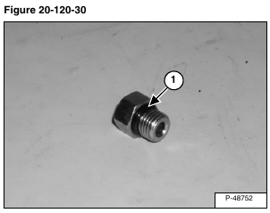
Inspect O-ring (Item 1) [Figure 20-120-30].
Assembly: Put oil on O-ring.
