Raise the lift arms and install an approved lift arm support device. (See Installing on Page 10-20-1.)
Raise the operator cab. (See Raising on Page 10-30-2.)
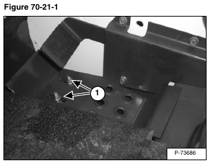
Remove the two mounting bolts (Item 1) [Figure 70-21-1] from the right side foot rest.
Remove the foot rest, from the loader.
Remove the two screws from the mount (Item 1) [Figure 70-21-2].
Remove the rubber grommet (Item 2) [Figure 70-21-2].
Installation: Tighten screws to 15 – 20 ft.-lb. (20 – 27 N•m) torque.
Disconnect the foot speed control linkage (Item 1) [Figure 70-21-3] from the hand control pivot arm.
Remove the foot speed control assembly from the loader.
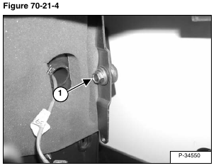
Remove the bolt and nut (Item 1) [Figure 70-21-4] from the hand speed control pivot arm.
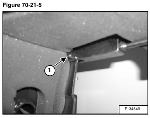
Remove the keeper and pin (Item 1) [Figure 70-21-5] that attaches the pivot arm to the speed control cable.
Remove the speed control pivot arm from the loader.
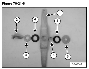
The parts that go into the pivot arm (Item 1) are the bolt (Item 2), washers (Items 3), fiber washers (Items 4), and spacer (Item 5) [Figure 70-21-6].
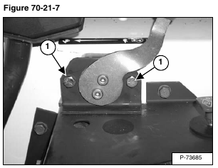
Remove the two screws (Item 1) [Figure 70-21-7] from the hand speed control lever assembly.
Installation: Tighten screws to 15 – 20 ft.-lb. (20 – 27 N•m) torque.
At the bottom side of the control panel, move the speed control linkage toward the rear of the loader.
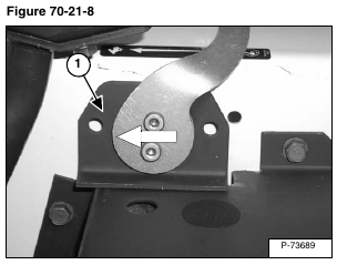
Slide the hand speed control lever (Item 1) [Figure 70-21-8] forward and lift, and disconnect the assembly from the speed control rod clevis.
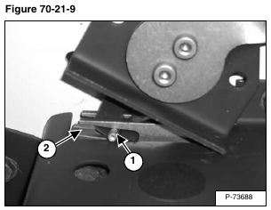
Installation: When installing the hand speed control, be sure the speed control lever and pin (Item 1) fit in the notch (Item 2) [Figure 70-21-9] of the speed control rod clevis..
