Raise the lift arms and install an approved lift arm device. (See Installing on Page 10-20-1.)
Raise the operator cab. (See Raising on Page 10-30-2.)
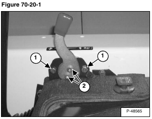
Remove the two mounting screws (Item 1) [Figure 70-20-1] from the speed control mounting bracket.
Installation: Tighten screws to 15 – 20 ft.-lb. (20 – 27 N•m) torque.
Installation: Tighten the mounting bolts (Item 2) [Figure 70-20-1] evenly until the speed control lever moves back and forth at a comfortable tension.
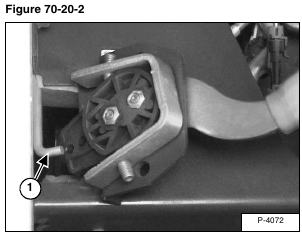
Pull the speed control away from the loader frame and disconnect the speed control rod (Item 1) [Figure 70-20-2] from the control.
Installation: Be sure to install the speed control rod in the bottom hole of the speed control lever.
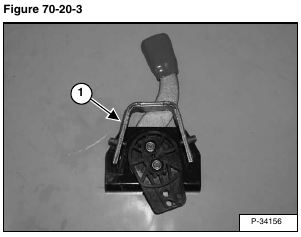
Installation: Install the stop bracket (Item 1) [Figure 70-20-3] in the same location. It is necessary for the front and rear stop on the bracket to be located correctly.
Reverse the removal procedure to install the engine speed control.


