Raise the lift arms and install an approved lift arm support device. (See Installing on Page 10-20-1.)
Raise the operator cab. (See Raising on Page 10-30-2.)
Remove the engine speed control. (See Removal And Installation on Page 70-20-1.)
Loosen the jam nut (Item 1) from the bypass control knob (Item 2) [Figure 50-100-2].
Remove the control knob (Item 2), jam nut (Item 1) and rubber washer (Item 3) [Figure 50-100-2].
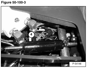
Disconnect the control harness connectors (Item 4) [Figure 50-100-2] & [Figure 50-100-3] from the control levers.
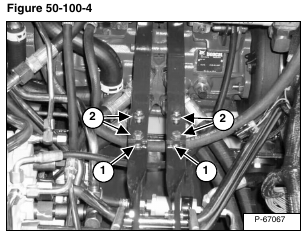
Scribe a mark across the top of the steering linkage bars (Item 1) [Figure 50-100-4] which are connected to the steering shaft on the control panel.
Remove the four steering linkage mounting bolts (Item 2) [Figure 50-100-4].
Installation: Align the marks on the steering linkage bars. Tighten the steering linkage mounting bolts to 35 – 40 ft.-lb. (47,5 – 54,2 N•m) torque.
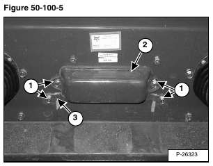
Remove the fuse/relay mounting bolts (Item 1) [Figure 50-100-5].
Remove the fuse/relay cover (Item 2) and fuse/relay block retaining bracket (Item 3) [Figure 50-100-5].
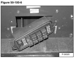
Remove the fuse/relay block [Figure 50-100-6].
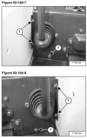
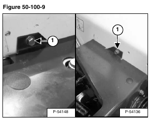
Remove the control panel mounting bolts (Item 1) [Figure 50-100-7], [Figure 50-100-8] & [Figure 50-100-9] from both sides of the control panel.
Installation: Tighten the control panel mounting bolts to 15 – 20 ft.-lb. (20 – 27 N•m) torque.
Remove the control panel from the loader.
Reverse the removal procedure to install the control panel.

