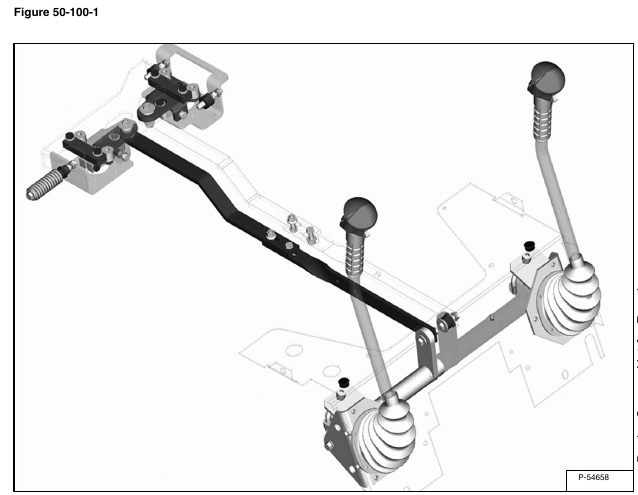
The steering system [Figure 50-100-1] consists of independent steering levers the operator uses to provide steering input to the loader.
The steering levers are attached to pivoting bellcranks that pivot on a steering shaft and plastic bushings. The bellcranks have grease fittings.
The forward travel is adjusted by drift adjustment bolts.
The bellcranks are attached to steering linkage bars with rubber torsion bushings pressed into the bellcranks.
Bellcranks mount to the control panel.
Steering linkage bars are a two-piece design. Steering linkage bars are adjustable in length for “full travel adjustment”.
Steering linkage bars attach to the pintle arms where a rubber torsion bushing is pressed into the pintle arms.
Pintle arms are of a two-piece design that allow easy adjustment of the neutral or “creep”.
The steering system returns the levers to their starting position by means of the centering spring and the returning force of the torsion bushings.
NOTE: Torsion bushings need to be replaced if torn or rotating in the housing. Loosen torsion bushing bolts slightly before adjustments are made. Do not fully tighten torsion bushing bolts again until all steering adjustments have been made first.
Sequence of steering adjustments:
1. Set neutral of pintle arms, “creep”
2. Set linkage travel at steering linkage bars
3. Set drift at drift adjustment bolts
