Remove the bolt (Item 1) from the pintle solid cams (Item 2) [Figure 50-100-24] and inspect the pintle solid cams for damage or excessive wear.
Installation: Tighten the bolts to 35 – 40 ft.-lb. (47,5 – 54,2 N•m) torque.
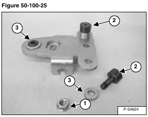
NOTE: The pintle roller cams (Item 2) [Figure 50-100-25] are used on ACS loaders only.
Remove the nut (Item 1) from the pintle roller cams (Item 2) and inspect the pintle roller cams and washers (Item 3) for damage [Figure 50-100-25].
Inspect the torsion bushing (Item 3) [Figure 50-100-25] for damage and replace as needed.
Installation: Tighten the nuts to 35 – 40 ft.-lb. (47,5 – 54,2 N•m) torque.
Remove the base pintle (Item 1) [Figure 50-100-26] from the pump shaft.
Remove the retaining bolt (Item 2), adjusting screw (Item 3) and neoprene dampener (Item 4) [Figure 50-100-26] from the base pintle.
Inspect parts for wear and damage, replace as needed [Figure 50-100-26].
NOTE: Anti-sieze should be used on the adjusting screw to prevent corrosion and allow free movement while adjusting.
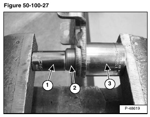
Using a bushing driver (Item 1) remove the torsion bushing (Item 2) by pressing the bushing through the pintle arm into an oversized socket (Item 3) to catch the torsion bushing [Figure 50-100-27].
Installation: Install the torsion bushing (Item 2) [Figure 50-100-27] into the pintle arm using the same procedure as the removal.
NOTE: When the torsion bushing is installed, the amount of bushing on each side of the pintle arm should be the same.


