The following tool listed will be needed to do the following procedure:
MEL1563 or 6689779 – Remote Start Tool Kit
Connect the remote start tool to the engine harness. (See REMOTE START TOOL KIT-MEL1563 on Page 10-60-1.)
Lift and block the loader. (See Procedure on Page 10-10-1.)
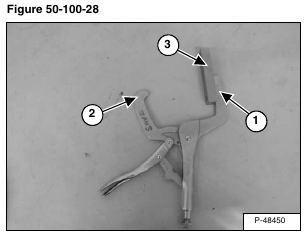
Tool that may assist in the neutral adjustment [Figure 50-100-28].
To make this tool use a locking grip C-Clamp and grind one edge flat (Item 1) and grind the other edge (Item 2) [Figure 50-100-28] to a small rounded edge.
A steering centering block (Item 3) [Figure 50-100-28] is also needed. The centering block can be placed as shown and welded to the C-clamp if desired.
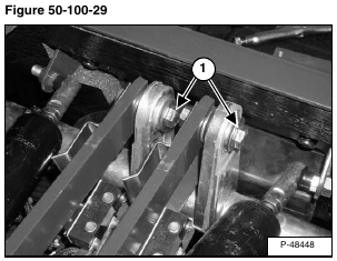
Loosen the bolt/nut (Item 1) [Figure 50-100-29] only until the tension is released from the torsion bushing.
Loosen the nut (Item 1) only until the tension is released from the torsion bushing (Item 2) [Figure 50-100-30].
NOTE: The bolt must be loose enough to allow the torsion bushing (Item 2) [Figure 50-100-30] to
turn freely between the torsion bushing and the steering linkage bar.
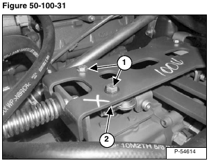
Loosen the two bolts (Item 1) holding the right centering block. Move the right hand centering block (Item 2) [Figure 50-100-31] until both pintle cams contact the centering block.
NOTE: The left centering block is not adjustable. By adjusting the right centering block the left centering block will also become aligned properly.
A modified locking grip C-Clamp and steering block shown in [Figure 50-100-28] may be used to help in aligning the centering blocks.
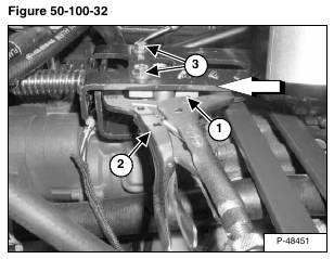
Install the centering block (Item 1) on the inside of the pintle cams and the C-Clamp (Item 2) [Figure 50-100-32] around both centering blocks.
Lock the C-Clamp in place.
Using the remote start tool, turn the key (Item 1) [Figure 50-100-33] to the run position.
Move the traction lock override switch (Item 2) [Figure 50-100-33] so the traction function is unlocked. (The traction lock override switch light will be ON.) On a standard loader the wedge brake will unlock.
NOTE: When the engine is started, the wheels/tracks may begin to move.
NOTE: In loaders equipped with manual steering and hydraulic brake, the steering levers may have to be moved during engine start-up to reduce the amount of creep. This reduction in creep will allow time for the engine to run and build up hydraulic charge pressure, which will release the hydraulic brake.
Using the remote start tool, turn the key (Item 1) [Figure 50-100-33] and start the engine and run at low idle.
Tighten bolts (Item 3) [Figure 50-100-32] to 35 – 40 ft.-lb. (47,5 – 54,2 N•m).
NOTE: Check for slack between centering blocks and pintle cams. If there is excessive slack repeat above steps [Figure 50-100-31] & [Figure 50-100-32].
Start the neutral adjustment procedure with the left pump first and complete the neutral adjustment for the left pump before adjusting the right pump.
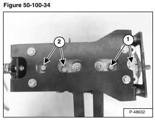
Loosen the left pump pintle adjustment lock bolts (Item 1). (The right pump pintle adjustment lock bolts are (Item 2) [Figure 50-100-34].) Loosen the bolts enough to allow free movement between the pintle arm and the pintle base.
NOTE: If the bolts are too loose or too tight, the neutral adjustment may be affected.
Move the engine speed control to high idle.
NOTE: The neutral range (dead-band) will vary between the hydrostatic pumps.
NOTE: This procedure is shown for neutral adjustment on the left side of the loader. The procedure is the same for the right side neutral adjustment.
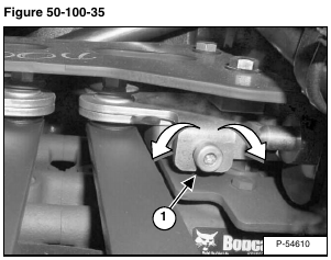
Turn the adjustment screw (Item 1) [Figure 50-100-35] counterclockwise until forward creep is seen.
Turn the adjustment screw (Item 1) [Figure 50-100-35] counterclockwise to a point between forward and reverse where there is zero creep.
Stroke the left steering lever to forward and allow the lever to return to neutral. Stroke the left steering lever to reverse and allow the lever to return to neutral. Check that there is zero creep when the lever returns from either direction, on the left side. Turn the adjustment screw (if necessary) until zero creep is obtained.
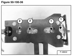
Torque the left pump pintle adjustment lock bolts (Item 1) [Figure 50-100-36] to 35 – 40 ft.-lb. (47,5 – 54,2 N•m).
Repeat the adjustment procedure for the right pump.
Torque the right pump pintle adjustment lock bolts (Item 2) [Figure 50-100-36] to 35 – 40 ft.-lb. (47,5 – 54,2 N•m).
Test both levers by moving them backward and forward and letting them return to neutral by the return spring force.
If the levers do not return to neutral and the wheels/tracks do not come to a complete stop, repeat the adjustment procedure again.
Stop the engine.
Remove one pintle adjustment bolt (Item 1) [Figure 50-100-36] at a time and apply Loctite® 242 or equivalent thread locker to the bolt and re-install the bolt. Torque the bolt to 35 – 40 ft.-lb. (47,5 – 54,2 N•m). Repeat for the three remaining pintle adjustment lock bolts.
NOTE: To maintain proper adjustment setting, remove and reinstall only one bolt at a time.
New bolts can be installed with pre applied Loctite®.
Remove the loader remote start tool.
NOTE: After the neutral adjustment is completed on both pumps, the linkage travel adjustment MUST be completed. (See Linkage Travel Adjusting on Page 50-100-17.)
