Raise the loader lift arms and install an approved lift arm support device. (See Installing on Page 10-20-1.)
Raise the loader operator cab. (See Raising on Page 10-30-2.)
Remove the control panel. (See Removal and Installation on Page 50-100-2.)
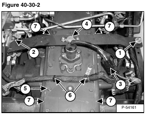
Disconnect the lift control cross bar from the lift pedal linkage (Item 1) [Figure 40-30-2].
Disconnect the lift control cross bar (Item 2) [Figure 40-30-2] from the lift spool on the main control valve.
Disconnect the electrical connector (Item 3) [Figure 40-30-2] from the traction lock solenoid.
Remove the crossbar mounting bolt (Item 4) [Figure 40-30-2] and remove the crossbar.
Remove the chaincase cover mounting screws (Item 5) [Figure 40-30-2].
Remove the tie straps (Item 6) [Figure 40-30-2] and remove the center chaincase cover.
NOTE: There are machined recesses (Item 7) [Figure 40-30-2] on the bottom side of the cover to help pry the cover off.
Installation: Apply polyurethane sealer to mating surfaces. Polyurethane sealant should be applied to the screw threads to stop oil leakage. Tighten the mounting screws to 20 – 25 ft.-lb. (27 – 34 N•m) torque.
