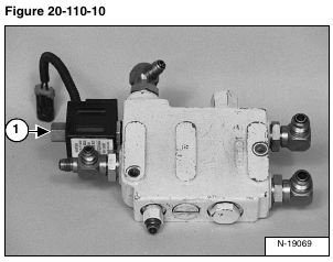
Remove the solenoid nut (Item 1) [Figure 20-110-10].
Installation: Tighten the solenoid nut to maximum 6 ft.- lb. (8 N•m) torque.
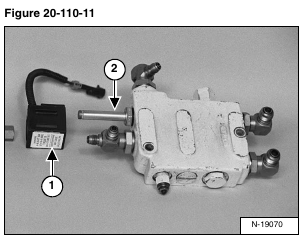
Remove the solenoid (Item 1) and the solenoid stem (Item 2) [Figure 20-110-11].
Installation: Put oil on O-rings and back-up washers and tighten the solenoid stem to 30 – 40 ft.-lb. (40,7 – 50,2 N•m) torque.
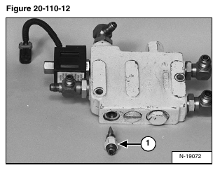
Remove the flow adjustment valve and O-ring (Item 1) [Figure 20-110-12].
Installation: Tighten the flow adjustment valve to 15 – 30 ft.-lb. (20,3 – 40,7 N•m) torque.
NOTE: Always install new O-rings before any parts are installed into the valve. Check the parts for wear or damage and replace as needed.
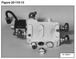
Remove the plug [Figure 20-110-13].
Assembly: Tighten the plug to 56 – 64 ft.-lb. (75,9 – 86,8 N•m) torque.
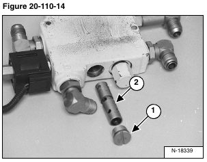
Remove the plug (Item 1), and flow control spool (Item 2) [Figure 20-110-14].
Assembly: Tighten the plug to 56 – 64 ft.-lb. (75,9 – 86,8 N•m) torque.
Check the flow control spool for wear, check the O-ring on the plug and replace as needed.
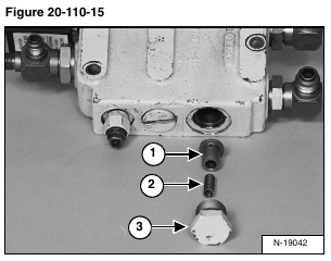
Remove the tilt cylinder check valve (Item 1) spring (Item 2) and plug (Item 3) [Figure 20-110-15]. Check for wear, check the O-ring and replace as needed.
Assembly: Tighten the plug to 56 – 64 ft.-lb. (75,9 – 86,8 N•m) torque.
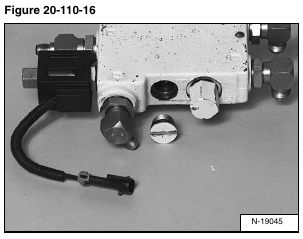
Remove the plug [Figure 20-110-16].
Assembly: Tighten the plug to 56 – 64 ft.-lb. (75,9 – 86,8 N•m) torque.
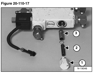
Remove the plug (Item 1), spring (Item 2) and unloading spool (Item 3) [Figure 20-110-17].
Check all parts and replace as needed. Install a new O-ring on the plug before installing.
Assembly: Tighten the plug to 56 – 64 ft.-lb. (75,9 – 86,8 N•m) torque.
