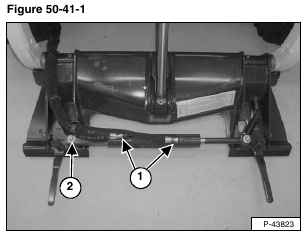
Tilt the Bob-Tach forward, so it is parallel to the floor. Put blocks (approximately 3 inches) under each side of the Bob-Tach [Figure 50-41-1].
Lower the Bob-Tach onto the blocks.
Remove the hoses on the cylinder fittings (Item 1) [Figure 50-41-1].
Remove the hose clamp on the hoses and use the bolt (Item 2) [Figure 50-41-1] on the Bob-Tach lever to secure the clamp.
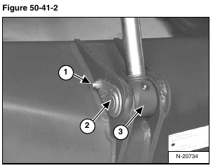
Remove the retainer bolt (Item 1) [Figure 50-41-2] and nut from the tilt cylinder rod end pin.
Installation: Tighten the retainer bolt and nut to 25 – 28 ft.-lb. (34 – 38 N•m) torque.
Remove the pivot pin (Item 2) [Figure 50-41-2] from the tilt cylinder rod end.
Remove the tilt cylinder rod end (Item 3) [Figure 50-41-2] from the Bob-Tach.
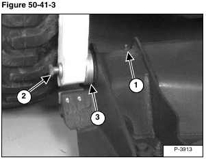
Remove the grease fitting (Item 1) [Figure 50-41-3] (Both sides). This will allow grease to come out in the next step. Not letting grease escape will prevent the pin from going into the Bob-Tach far enough to remove the Bob-Tach from the lift arms.
Loosen the bolt (Item 2) [Figure 50-41-3] at the Bob-Tach pivot pin. (Both sides)
Strike the head of the bolt (Item 2) [Figure 50-41-3] to push the pivot pin into the Bob-Tach frame. (Both sides)
Remove the bolt. (Both sides)
Installation: A longer bolt will be needed to temporarily reach through the lift arms into the pins to seat them into the lift arms. Once seated, reinstall the original bolts.
Tighten the bolts to 190 ft.-lb. (258 N•m) torque.
Use a punch to push the pivot pins all the way inside the Bob-Tach frame.
Remove the Bob-Tach from the lift arms.
Remove the dust cup (Item 3) [Figure 50-41-3] (Both sides) when the Bob-Tach is free from the loader.
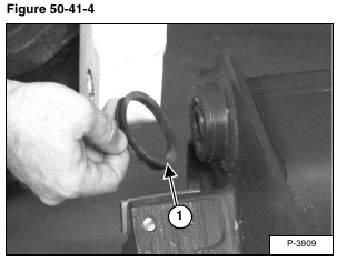
Remove the rubber seal (Item 1) [Figure 50-41-4] (Both sides).
Installation: Use a new seal when assembling.
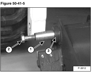
Remove the Bob-Tach pivot pin (Item 1). (Both sides) Thread the bolt (Item 2) [Figure 50-41-5] into the pivot pins and pull.
Check for wear and damage on the pins and the Bob-Tach bushings (Item 3) [Figure 50-41-5]. Replace as needed.
Reverse the removal procedure to install the Bob-Tach.
