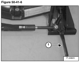
Use the following procedure to remove and install the Bob-Tach lever (Item 1) [Figure 50-41-6], spring and wedge.
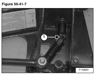
Use a punch and hammer, remove the roll pin (Item 1) [Figure 50-41-7] from the Bob-Tach Wedge and spring clevis.
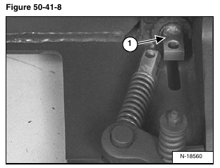
Remove the Wedge (Item 1) [Figure 50-41-8].
Always replace bent or broken wedges.
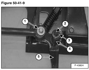
Remove the washer and bolt (Item 1) [Figure 50-41-9].
Installation: Tighten the bolts to 25 – 28 ft.-lb. (34 – 38 N•m) torque.
Remove the cylinder off the lever pivots. Position the rod end to the left with the grease fitting holes to the bottom [Figure 50-41-9].
Remove the lever mounting nut (Item 2), washer (Item 3), spring (Item 4) and lever (Item 5) [Figure 50-41-9].
Installation: Tighten the nut to 25 – 28 ft.-lb. (34 – 38 N•m) torque.
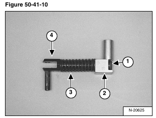
If the bolt (Item 1), handle pivot (Item 2), spring (Item 3) or clevis (Item 4) [Figure 50-41-10] are damaged, put the assembly in a vise.
Remove the bolt and replace the damaged parts as needed.
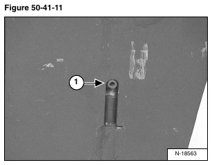
Use a punch and hammer to drive the roll pin (Item 1) [Figure 50-41-11] flush with the face of the Bob-Tach.
Reverse the removal procedure to install the Power Bob-Tach lever and wedge.
