Clean all parts in solvent and dry with compressed air.
Inspect the parts for wear or damage. Replace any worn or damaged parts.
Always install new O-rings and seals.
Lubricate all O-rings and seals with hydraulic oil during installation.
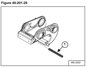
Install the compression spring (Item 1) [Figure 40-201-29].
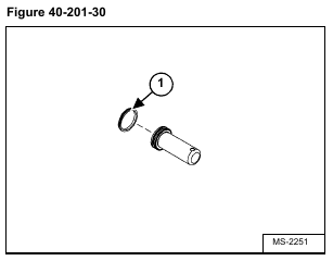
Install the piston seal (Item 1) [Figure 40-201-30] on the piston.
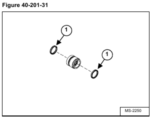
Install the two pin seals (Item 1) [Figure 40-201-31] on the inside of the piston head.
Install the O-ring (Item 1) and back-up ring (Item 2) [Figure 40-201-32] on the piston head.
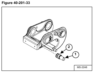
Install the piston (Item 1) and the piston head (Item 2) [Figure 40-201-33].
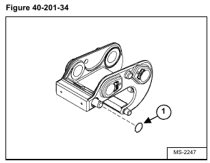
Apply inward pressure on the piston and install the retaining ring (Item 1) [Figure 40-201-34].
Repeat [Figure 40-201-30 on Page 9] through [Figure 40-201-34] to remove the piston head and piston from the opposite side of the X-change.
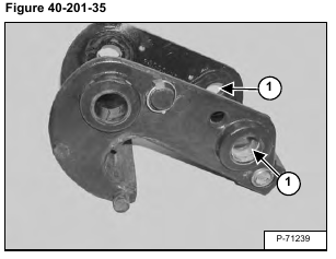
Install the bushings (Item 1) [Figure 40-201-35].
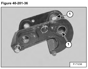
Install the bushings (Item 1) [Figure 40-201-36].
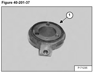
Install the dust seal (Item 1) [Figure 40-201-37] on the swivel.
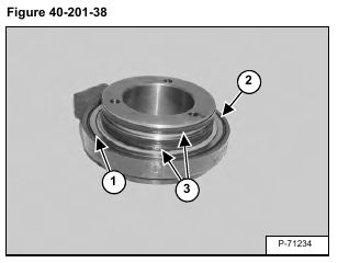
Install the O-ring (Item 1) wear ring (Item 2) and seals (Item 3) [Figure 40-201-38].
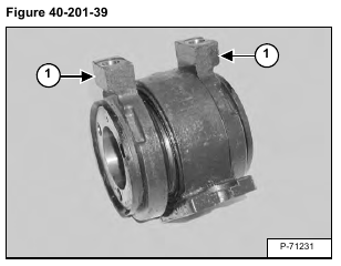
Install the swivel ends (Item 1) [Figure 40-201-39] onto the base.
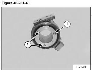
Install the screws (Item 1) [Figure 40-201-40] and nuts in the swivel assembly. Do not tighten at this time.
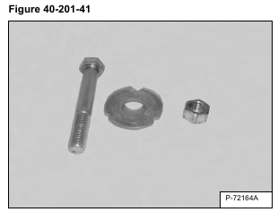
It is necessary to fabricate a preload tool to get the proper torque on the swivel assembly screws. The tool consists of a 15,9 x 127 mm (5/8 x 5 in) course thread bolt, two 15,9 x 50,8 mm (5/8 x 2 in) flat washers and a 5/8 course thread nut [Figure 40-201-41].
NOTE: This procedure must be followed to ensure the swivel assembly screws are tightened to the
proper torque value.
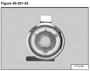
Center a 50,8 mm (2 in) flat washer on one side of the swivel assembly [Figure 40-201-42].
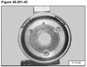
Using a marker, mark the three screw holes on the washer [Figure 40-201-43].
Repeat for the opposite side.
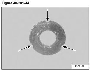
Using a grinder, remove material identified in the previous step [Figure 40-201-44].
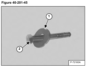
Install a 50,8 mm (2 in) flat washer (Item 1) onto the bolt (Item 2) [Figure 40-201-45].
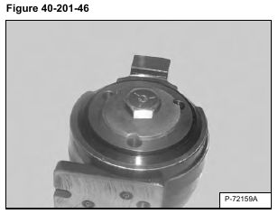
Insert the bolt through the center of the swivel assembly aligning the notches in the flat washer with the screw holes [Figure 40-201-46].
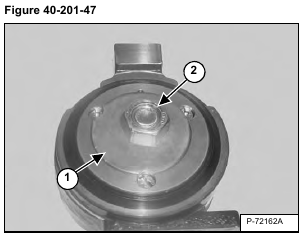
Turn the swivel assembly over and install the remaining 50,8 mm (2 in) flat washer (Item 1) and nut (Item 2) [Figure 40-201-47].
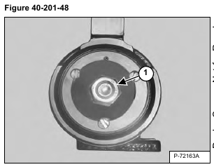
NOTE: The notches in both washers must be aligned with the screw holes on the swivel assembly [Figure 40-201-48].
Tighten the preload tool nut (Item 1) [Figure 40-201-48] to 112,5 N•m (83 ft-lb) torque.
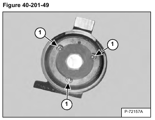
Tighten the swivel assembly screws (Item 1) [Figure 40-201-49] to 14,2 – 15,8 N•m (10.4 – 11.6 ft-lb) torque.
Remove the preload tool.
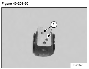
Install the two O-rings (Item 1) [Figure 40-201-50] into the swivel assembly.
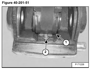
Install the swivel assembly (Item 1) using the bolt (Item 2) [Figure 40-201-51].
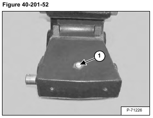
Install the bolt (Item 1) [Figure 40-201-52] and nut.
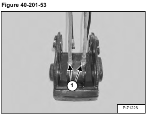
Install the hydraulic hoses (Item 1) [Figure 40-201-53] onto the swivel ends.
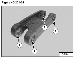
Install the bushings (Item 1) [Figure 40-201-54] and dust seals into the bucket link.
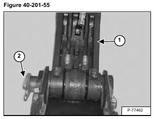
Install the bucket link (Item 1) and pin (Item 2) [Figure 40-201-55].
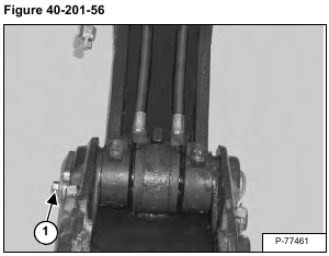
Install the spacer, flat washer and bolt (Item 1) [Figure 40-201-56].
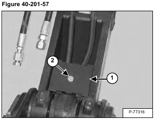
Install the foam block and cover (Item 1) using the bolt (Item 2) [Figure 40-201-57] and nut.
