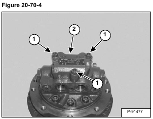
Remove the three bolts (Item 1) and remove the valve (Item 2) [Figure 20-70-4].
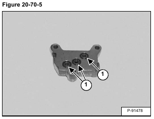
Remove the O-rings (Item 1) [Figure 20-70-5].
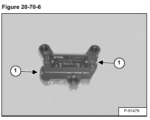
Remove the plugs (Item 1) [Figure 20-70-6].
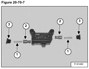
Remove the springs (Item 1) and poppets (Item 2).
Remove the O-rings (Item 3) [Figure 20-70-7] from the plugs.
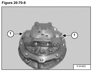
Remove the plugs (Item 1) [Figure 20-70-8].
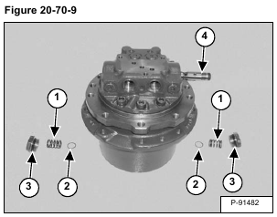
Remove the springs (Item 1) and spring seats (Item 2).
Remove the O-rings (Item 3) from the plugs. Remove the spool (Item 4) [Figure 20-70-9] from the housing.
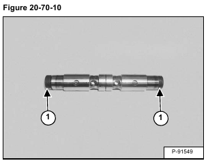
Heat the plugs (Item 1) [Figure 20-70-10] to melt the thread adhesive and remove the plugs from both ends of the spool.
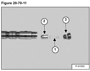
Remove the spring (Item 1) and check valve (Item 2) from both ends of the valve. Remove the O-ring (Item 3) [Figure 20-70-11] from both plugs.
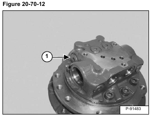
Remove the plug (Item 1) [Figure 20-70-12].
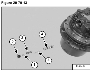
Remove the spring seat (Item 1), spring (Item 2), inner spool (Item 3) and outer spool (Item 4). Remove the O-ring (Item 5) [Figure 20-70-13] from the plug.
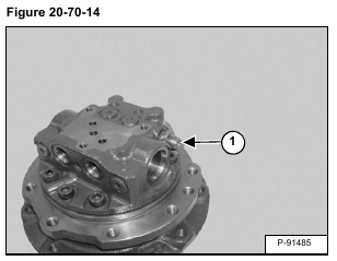
Remove the fitting (Item 1) [Figure 20-70-14].
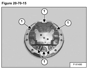
Remove the bolts (Item 1) [Figure 20-70-15] and remove the end cap.
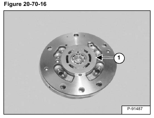
Remove the valve plate (Item 1) [Figure 20-70-16].
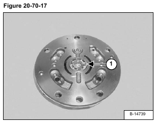
Remove the bearing (Item 1) [Figure 20-70-17].
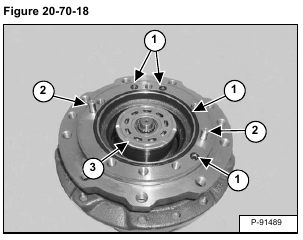
Remove the O-rings (Item 1). Remove the dowel pins (Item 2) [Figure 20-70-18].
Remove the rotating group (Item 3) [Figure 20-70-18].
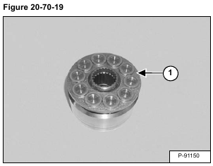
Remove the piston assemblies / retainer (Item 1) [Figure 20-70-19] from the cylinder block.
NOTE: It is not important that the pistons are installed in the original bores.
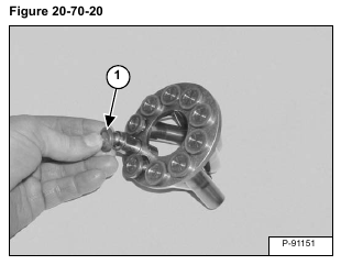
Remove the piston assemblies (Item 1) [Figure 20-70-20] from the retainer.
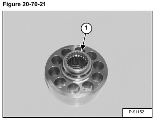
Remove the ball guide (Item 1) [Figure 20-70-21].
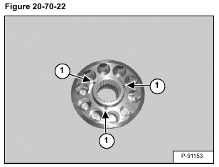
Remove the three pins (Item 1) [Figure 20-70-22].
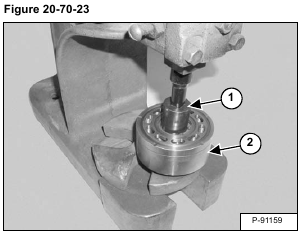
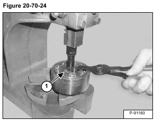
Using a press and an appropriate sized spacer (Item 1), compress the spring in the cylinder block (Item 2) [Figure 20-70-23].
Remove the snap ring (Item 1) [Figure 20-70-24].
Remove the cylinder block from the press.
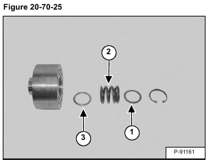
Remove the top washer (Item 1), spring (Item 2) and bottom washer (Item 3) [Figure 20-70-25].
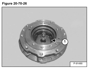
Remove the swash plate (Item 1) [Figure 20-70-26].
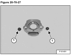
Remove the steel balls (Item 1) [Figure 20-70-27] from the bottom of the swash plate.
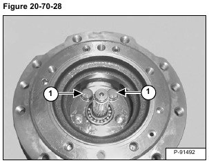
Remove the piston assemblies (Item 1) [Figure 20-70-28].
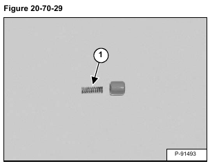
Remove the spring (Item 1) [Figure 20-70-29] from the piston.
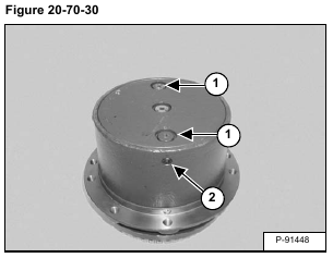
Remove the two plugs (Item 1) from the cover. Remove the pipe plug (Item 2) [Figure 20-70-30].
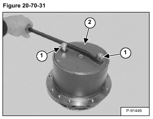
Install a cap and fitting (Item 1) in both ports. Use a bar between the fittings and turn the cover (Item 2) [Figure 20-70-31].
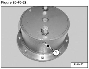
Turn the cover until the wire (Item 1) [Figure 20-70-32] is visible in the pipe plug hole. Pull the end of the wire out of the housing.
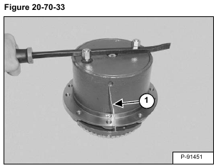
Continue to turn the cover in a counter clockwise direction while pulling the wire (Item 1) [Figure 20-70-33] out of the housing.
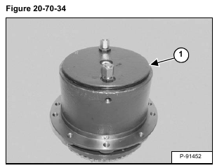
After the wire is fully removed lift up on and remove the cover (Item 1) [Figure 20-70-34].
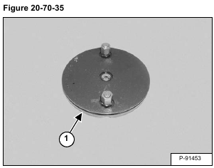
Remove the O-ring (Item 1) [Figure 20-70-35] from the cover.
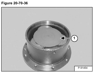
Remove the thrust plate (Item 1) [Figure 20-70-36].
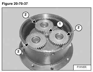
Remove the sun gear (Item 1) and planetary gears (Item 2) [Figure 20-70-37].
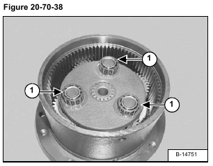
Remove the bearings (Item 1) [Figure 20-70-38].
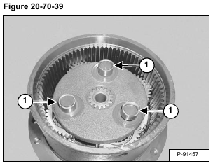
Remove the bearing inner races (Item 1) [Figure 20-70-39].
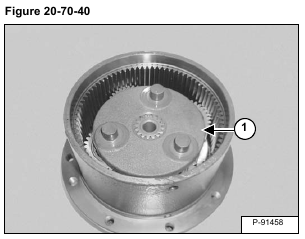
Remove the planetary gear carrier (Item 1) [Figure 20-70-40].
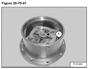
Remove the sun gear (Item 1) [Figure 20-70-41].
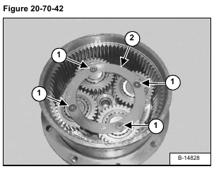
Heat the screw heads (Item 1) to melt the thread adhesive. Remove the screws and thrust plate (Item 2) [Figure 20-70-42].
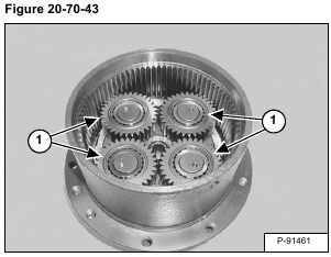
Remove the planetary gears (Item 1) [Figure 20-70-43].
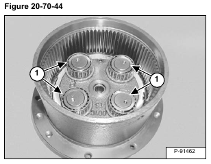
Remove the bearings (Item 1) [Figure 20-70-44].
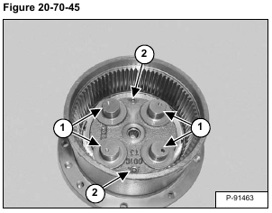
Remove the thrust washers (Item 1). Remove the plugs (Item 2) [Figure 20-70-45].
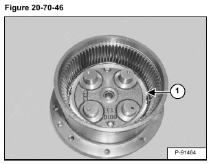
Remove the nut (Item 1) [Figure 20-70-46].
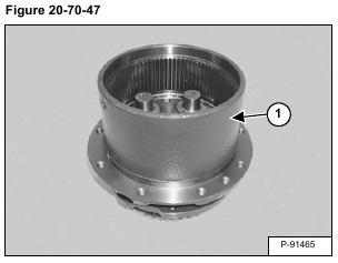
Remove the housing (Item 1) [Figure 20-70-47] from the hub.
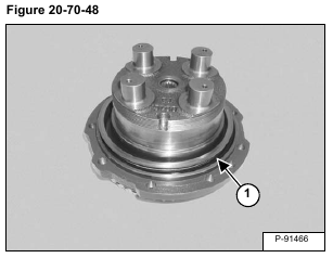
Remove the floating seal (Item 1) [Figure 20-70-48].
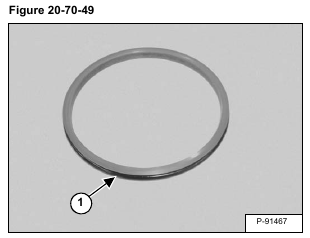
Remove the O-ring (Item 1) [Figure 20-70-49] from the seal ring.
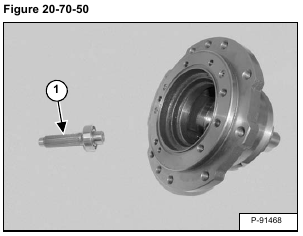
Remove the shaft / bearing assembly (Item 1) [Figure 20-70-50].
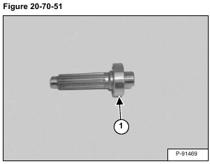
Remove the bearing (Item 1) [Figure 20-70-51] from the shaft.
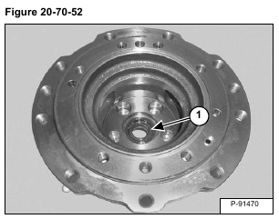
Remove the seal (Item 1) [Figure 20-70-52].
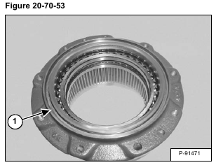
Remove the floating seal (Item 1) [Figure 20-70-53].
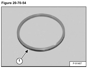
Remove the O-ring (Item 1) [Figure 20-70-54] from the seal ring.
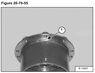
Remove the plug (Item 1) [Figure 20-70-55].
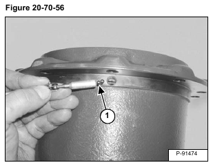
Remove the steel balls (Item 1) [Figure 20-70-56] retaining the bearing to the housing.
NOTE: There are 132 steel balls.
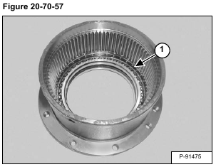
After all the steel balls have been removed, tap the bearing (Item 1) [Figure 20-70-57] out of the housing.
