Clean all parts in solvent and dry with compressed air.
Inspect all parts and replace any that are damaged.
Apply oil to all O-rings (as noted) and light grease to the ball and roller bearings before installation.
The following tools will be needed to assemble the travel motor:
MEL1412 – Seal Installation Tool
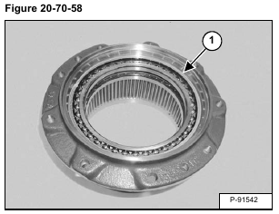
Install the bearing (Item 1) [Figure 20-70-58] in the housing.
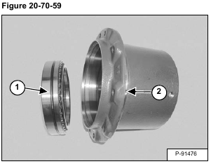
Seat the bearing until the groove (Item 1) in the bearing race is visible through the hole (Item 2) [Figure 20-70-59] in the housing.
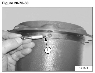
Install the steel balls (Item 1) [Figure 20-70-60].
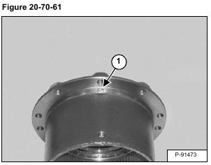
Install the plug (Item 1) [Figure 20-70-61].
Tighten the plug to 6,8 – 8,8 N•m (4.4 – 7.2 ft-lb) torque.
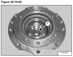
Install the oil seal (Item 1) [Figure 20-70-62].
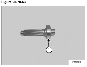
Install the bearing (Item 1) [Figure 20-70-63].
Install the shaft / bearing assembly in the hub (Item 1) [Figure 20-70-64].
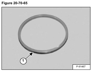
Install the O-ring (Item 1) [Figure 20-70-65] on the seal rings.
NOTE: Inspect the seal ring for burrs before installing the O-ring. Install the O-ring making sure it is not twisted. To remove any twists, gently pull a section of the O-ring and let it snap back.
The O-ring, seal rings, motor assembly and housing must be clean and free of any dust, oil film or foreign matter.
Install the seal seating tool (MEL1412) on the seal ring and O-ring assembly.
The O-ring and seal ring assembly has to be lubricated with alcohol so the O-ring will slip past the housing retaining ring and seal uniformly in the motor housing radius. Do not use oil to lubricate the O-ring.
Dip the O-ring and seal ring assembly in a pan of alcohol.
Shake off the excess alcohol and install the seal ring assembly on the hub [Figure 20-70-66].
Use firm even pressure on the installation tool (MEL1412) to install the O-ring in the motor housing.
Repeat the procedure for the housing.
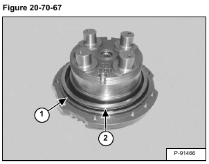
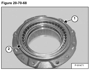
After the seal ring (Item 1) [Figure 20-70-67] and [Figure 20-70-68] is installed, check the stand out height in four places, 90° apart.
Apply a light film of oil to the seal ring lapped face (Item 2) [Figure 20-70-67] and [Figure 20-70-68].
Install the housing (Item 1) [Figure 20-70-69] on the hub.
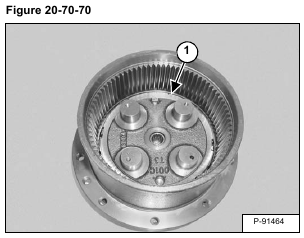
Install the nut (Item 1) [Figure 20-70-70].
Tighten the nut to 186,2 – 205,8 N•m (138 – 152 ft-lb) torque.
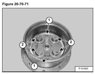
Install the plugs (Item 1). Tighten the plugs to 9,8 – 19,6 N•m (7.3 – 14.5 ft-lb) torque. Install the thrust washers (Item 2) [Figure 20-70-71].
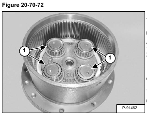
Install the bearings (Item 1) [Figure 20-70-72].
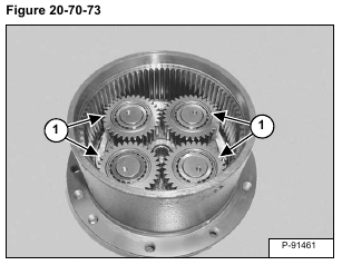
Install the gears (Item 1) [Figure 20-70-73].
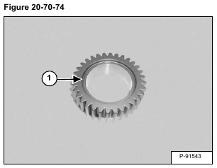
NOTE: Install the gears with the bevel (Item 1) [Figure 20-70-74] towards the thrust washer.
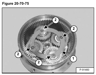
Install the thrust plate (Item 1). Apply Loctite® 271 to the threads of the screws (Item 2) [Figure 20-70-75]. Install and tighten the screws to 12,1 – 13,3 N•m (9 – 10 ft-lb) torque.
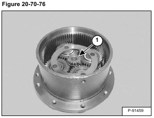
Install the sun gear / snap ring assembly (Item 1) [Figure 20-70-76].
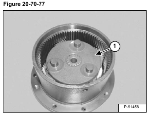
Install the planetary gear carrier (Item 1) [Figure 20-70-77].
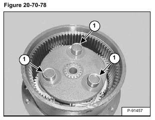
Install the races (Item 1) [Figure 20-70-78].
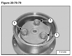
Install the bearings (Item 1) [Figure 20-70-79].
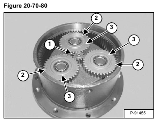
Install the sun gear (Item 1). Install the planetary gears (Item 2) [Figure 20-70-80].
NOTE: Install the gears with the thrust surface (Item 3) [Figure 20-70-80] towards the cover side of the motor.
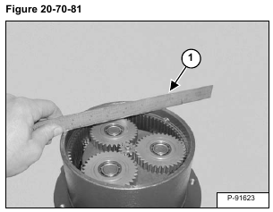
Place a straight edge (Item 1) [Figure 20-70-81] across the top of the housing.
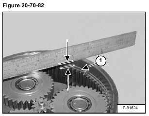
Measure down from the bottom of the straight edge to the top of the housing teeth (Item 1) [Figure 20-70-82].
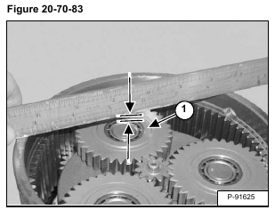
Measure down from the bottom of the straight edge to the thrust surface (Item 1) [Figure 20-70-83] on the top of the gear. Calculate the difference between the two measurements and select the correct thrust plate.
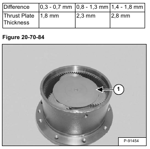
Install the correct thrust plate (Item 1) [Figure 20-70-84].
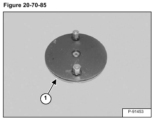
Install the O-ring (Item 1) [Figure 20-70-85] on the cover.
Install the cover with the cut out (Item 1) aligned with the hole (Item 2) in the housing. The lock wire (Item 3) is installed through the housing and the hook end of the wire must engage the cut out (Item 1) [Figure 20-70-86] on the cover.
Install the lock wire (Item 1) [Figure 20-70-87].
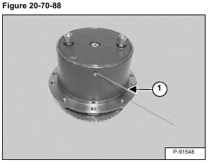
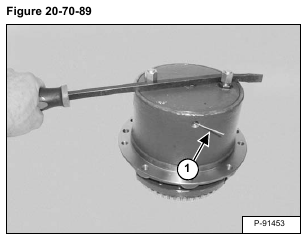
Rotate cover 3/4 of a turn clockwise. Cut off the remaining wire (Item 1) [Figure 20-70-88]. Continue to turn the cover until the wire (Item 1) [Figure 20-70-89] is inside the housing.
Install the plugs (Item 1) [Figure 20-70-90]. Tighten the plug to 6,8 – 8,8 N•m (4.4 – 7.2 ft-lb) torque.
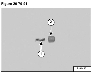
Install the springs (Item 1) in both of the pistons (Item 2) [Figure 20-70-91].
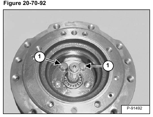
Install the piston / spring assembly (Item 1) [Figure 20-70-92] in the piston bores.
Install the steel balls (Item 1) in the sockets (Item 2) [Figure 20-70-93] on the swash plate.
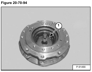
Install the swash plate assembly (Item 1) [Figure 20-70-94] in the housing.
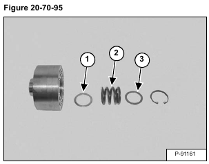
Install the bottom washer (Item 1), spring (Item 2) and top washer (Item 3) [Figure 20-70-95].
Using a press and an appropriate sized spacer (Item 1), compress the spring in the cylinder block (Item 2) [Figure 20-70-96].
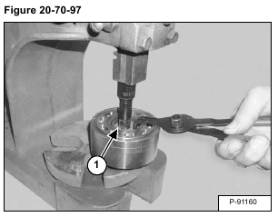
Install the snap ring (Item 1) [Figure 20-70-97] in the cylinder block. Remove the cylinder block from the press.
Install the three pins (Item 1) [Figure 20-70-98] in the cylinder block.
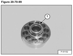
Install the ball guide (Item 1) [Figure 20-70-99].
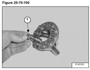
Install the piston assemblies (Item 1) [Figure 20-70-100] in the retainer.
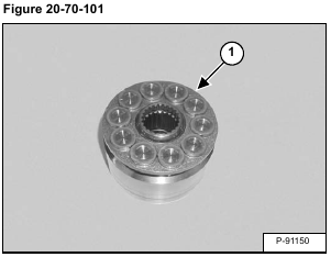
Install the piston assemblies / retainer (Item 1) [Figure 20-70-101] in the cylinder block.
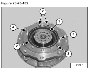
Install the rotating group (Item 1) in the housing. Install the O-rings (Item 2) and dowel pins (Item 3) [Figure 20-70-102].
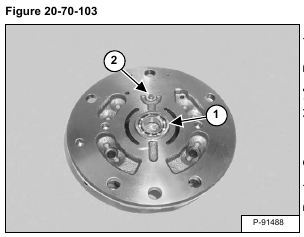
Install the bearing (Item 1). Install the pin (Item 2) [Figure 20-70-103].
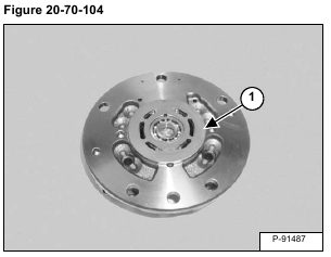
Install the valve plate (Item 1) [Figure 20-70-104].
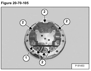
Install the end cap (Item 1) and bolts (Item 2) [Figure 20-70-105].
Tighten the bolts to 58,8 – 68,6 N•m (43.4 – 50.5 ft-lb) torque.
Install the outer spool (Item 1), inner spool (Item 2), spring (Item 3) and spring seat (Item 4). Install the O-ring (Item 5) on the plug (Item 6) [Figure 20-70-106].
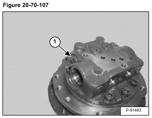
Install the plug (Item 1) [Figure 20-70-107]. Tighten the plug to 49 – 58,8 N•m (36.2 – 43.4 ft-lb) torque.
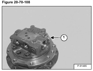
Install the fitting (Item 1) [Figure 20-70-108].
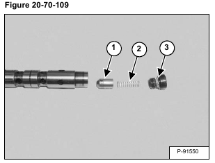
Install the check valves (Item 1) and springs (Item 2) in both ends of the spool. Install the O-rings (Item 3) [Figure 20-70-109] on the plugs.
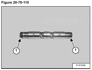
Apply Loctite® 271 to the plug threads and install the plugs (Item 1) [Figure 20-70-110]. Tighten the plugs to 21,8 – 34,4 N•m (16 – 25 ft-lb) torque.
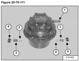
Install the spool (Item 1). Install the spring seats (Item 2) and springs (Item 3). Install the O-rings (Item 4) [Figure 20-70-111] on the plugs.
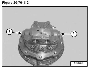
Install the plugs (Item 1) [Figure 20-70-112]. Tighten the plugs to 235 – 245 N•m (173 – 181 ft-lb) torque.
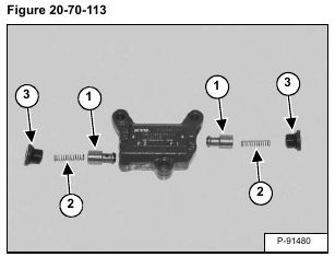
Install the poppets (Item 1) and springs (Item 2). Install the O-rings (Item 3) [Figure 20-70-113] on the plugs.
Install the plugs (Item 1) [Figure 20-70-114]. Tighten the plugs to 49 – 59 N•m (36 – 43 ft-lb) torque.
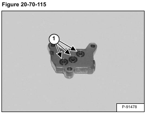
Install the O-rings (Item 1) [Figure 20-70-115].
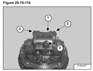
Install the valve (Item 1) on the motor. Install the bolts (Item 2) [Figure 20-70-116]. Tighten the bolts to 35 – 39 N•m (26 – 29 ft-lb) torque.
