Remove the right console cover. (See Console Cover Removal And Installation on Page 40-50-1.)
Cut and remove the cable tie (Item 1) [Figure 20-110-4].
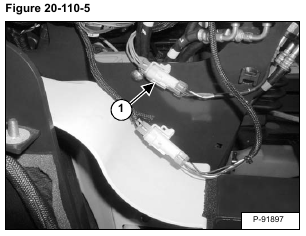
Disconnect the electrical connector (Item 1) [Figure 20-110-5] from the excavator wiring harness.
Remove the lock (Item 1) [Figure 20-110-6] from the electrical connector.
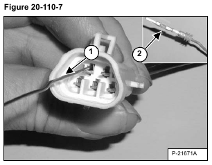
With a small piece of wire, depress the wire terminal tabs (Item 1) [Figure 20-110-7].
Carefully remove the individual wires from the back of the electrical connector.
Installation: Use a small piece of wire and re-bend the tab (Item 2) [Figure 20-110-7] on each wire before installing the electrical connector.
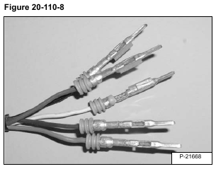
Installation: The wires [Figure 20-110-8] must be installed in the proper locations in the wire connector, listed below.
A Green
B Brown
C Red
D Black
E White
Check each wire to be certain the tab locks into position.
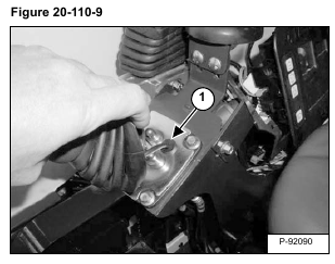
Raise the boot (Item 1) and pull the grommet (Item 2) [Figure 20-110-9] up out of the housing.
Remove the wire and grommet.
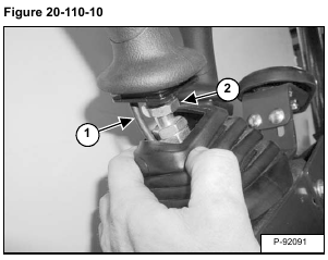
Pull the boot down and pull the wire harness (Item 1) out of the boot. Loosen the nut (Item 2) [Figure 20-110-10] and remove the handle.
Installation: Align the top of the dust boot (Item 1) with the groove (Item 2) [Figure 20-110-11].

