Clean all parts in solvent and dry with compressed air.
Inspect all parts for wear or damage. Replace any worn or damaged parts.
Always install new seals and O-rings. Lubricate all seals and O-rings with clean hydraulic fluid before installation.
Clamp the housing in a vise equipped with padded jaws.
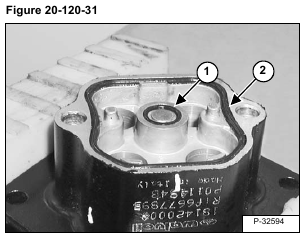
Install the O-ring (Item 1) and seal (Item 2) [Figure 20-120-31].
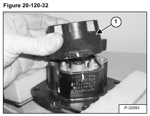
Install the end cap (Item 1) [Figure 20-120-32].
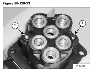
Install the bolts (Item 1) [Figure 20-120-33].
Turn the housing over.
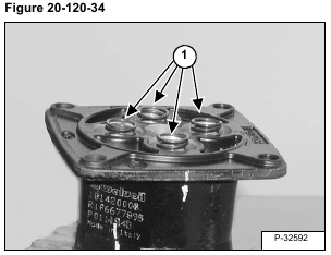
Install the springs (Item 1) [Figure 20-120-34].
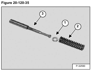
Install the shim (Item 1) and spring (Item 2) on the spool (Item 3) [Figure 20-120-35].
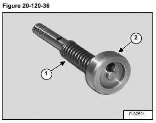
Compress the spring (Item 1) and install the spring seat (Item 2) [Figure 20-120-36].
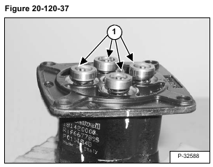
Install the spool assemblies (Item 1) [Figure 20-120-37] into the housing.
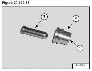
Install the O-ring (Item 1) into the bushing (Item 2). Install the plunger (Item 3) [Figure 20-120-38] into the bushing.
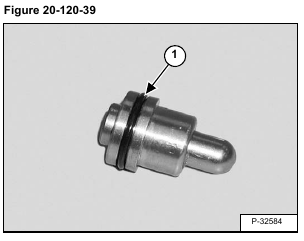
Install the O-ring (Item 1) [Figure 20-120-39] on the bushing.
Install the plunger assemblies (Item 1) [Figure 20-120-40] into the housing.
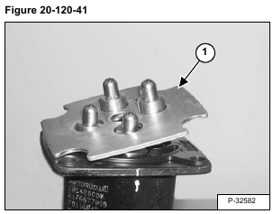
Install the plate (Item 1) [Figure 20-120-41].
NOTE: Spring pressure can dislodge the plunger assemblies until the plate is secured in place.
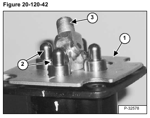
Press down on the plate (Item 1) keeping the plunger assemblies (Item 2) fully seated and install the U-joint (Item 3) [Figure 20-120-42].
Install the control plate (Item 1) until the plate makes light contact with all four plungers (Item 2) [Figure 20-120-43].
Align the coupler (Item 1) with the control plate (Item 2) and plate (Item 3) [Figure 20-120-44]. Tighten the coupler.
Install the connector (Item 1) [Figure 20-120-45].
Align the connector with the coupler (Item 2) and tighten the nut (Item 3) [Figure 20-120-45].
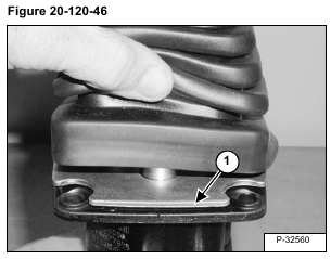
Install the tabs of the boot in between the joystick flange and the mounting plate (Item 1) [Figure 20-120-46].
Install the handle. (See Handle Removal And Installation on Page 20-120-2.)
