Remove the instrument panel / controller. (See Removal And Installation on Page 50-101-1.)
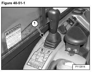
Remove the screw (Item 1) [Figure 40-51-1].
Pull the side cover (Item 1) away from the front cover (Item 2) [Figure 40-51-2].
Pull the front cover (Item 2) [Figure 40-51-2] towards the front of the excavator and remove the cover.
Installation: Install the tab (Item 1) [Figure 40-51-3] of the side cover into the front cover.
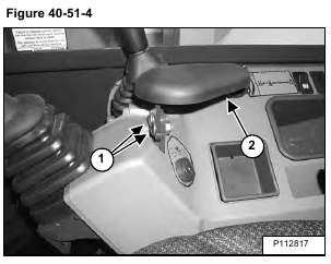
Remove the two bolts (Item 1) and nuts. Remove the arm rest (Item 2) [Figure 40-51-4].
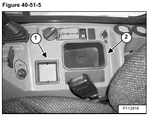
Pull up on and remove the storage containers (Item 1) and (Item 2) [Figure 40-51-5].
Note:
The excavator may be equipped with a radio instead of the storage container (Item 2) [Figure 40-51-5]. Pull up on and remove the radio.
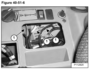
Disconnect the wire harness (Item 1) [Figure 40-51-6] from the engine speed control, switches and auxiliary power outlet.
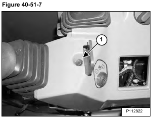
Pull up on the center pin (Item 1) [Figure 40-51-7].
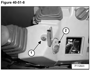
Remove the pin assembly (Item 1). Remove the nut (Item 2) [Figure 40-51-8] from the key switch. Lower the switch into the console.
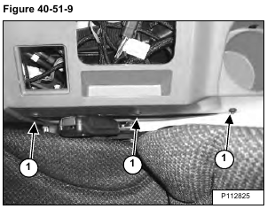
Pull up on the center pin (Item 1) [Figure 40-51-9].
Remove the pin assembly (Item 1) [Figure 40-51-10].
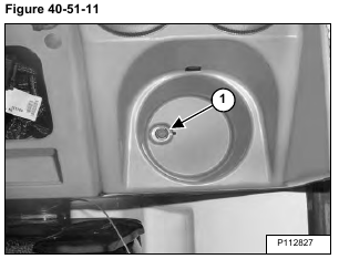
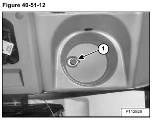
Pull up on the center pin (Item 1) [Figure 40-51-11].
Remove the pin assembly (Item 1) [Figure 40-51-12].
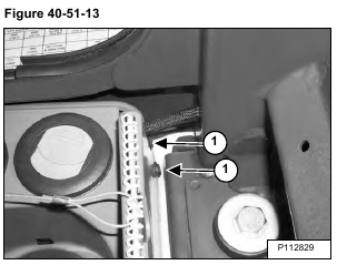
Pull up on the center pin (Item 1) [Figure 40-51-13].
Remove the pin assembly (Item 1) [Figure 40-51-14].
Loosen the nut (Item 1) [Figure 40-51-15] and bolt located under the console cover. Remove the cover.
