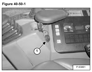
Remove the nut (Item 1) [Figure 40-50-1] from the key switch. Lower the switch into the console.
Remove the screw (Item 1) [Figure 40-50-2].
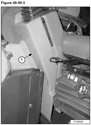
Pull the cover (Item 1) [Figure 40-50-3] towards the front of the excavator and remove the cover.
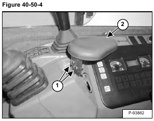
Remove the two bolts (Item 1) and nuts. Remove the arm rest (Item 2) [Figure 40-50-4].
Pull up on the center pin (Item 1) [Figure 40-50-5].
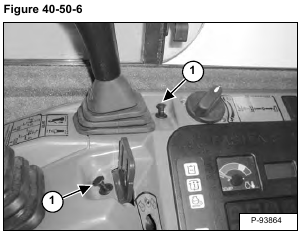
Remove the pin assembly (Item 1) [Figure 40-50-6].
Remove the two screws (Item 1). Remove the louver (Item 2) [Figure 40-50-7].
Pull up on the center pin (Item 1) [Figure 40-50-8].
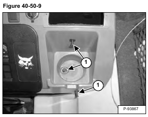
Remove the pin assembly (Item 1) [Figure 40-50-9].
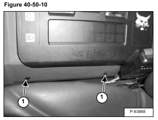
Pull up on the center pin (Item 1) [Figure 40-50-10].
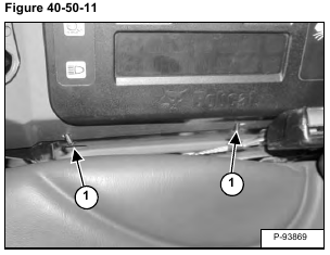
Remove the pin assembly (Item 1) [Figure 40-50-11].
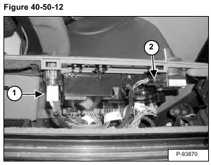
Tilt the cover forward and disconnect the auxiliary power outlet wire harness (Item 1) and the engine speed control wire harness (Item 2) [Figure 40-50-12].
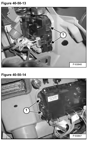
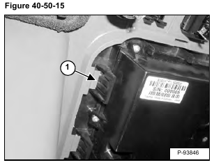
Depress the tabs (Item 1) [Figure 40-50-13] and [Figure 40-50-14] on the controller.
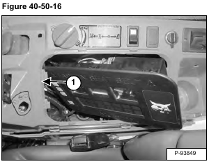
Installation: The tabs (Item 1) [Figure 40-50-15] must fully engage the console cover.
Remove the cover (Item 1) [Figure 40-50-16].
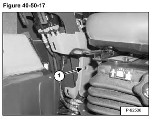
Pull up on the center pin (Item 1) [Figure 40-50-17].
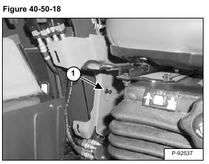
Remove the pin assembly (Item 1) [Figure 40-50-18].
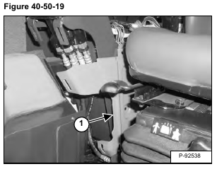
Remove the cover (Item 1) [Figure 40-50-19]
