The testing of the piston pump must be done in the following order:
Pump Margin Pressure Adjustment
Main Relief Valve Adjustment
Torque Limiter Adjustment
Direct Gear Pump Test
Test Fitting Installation
The following tools will be needed to do the procedure:
MEL10003 – Hydraulic Tester
3447 kPa (34 bar) (500 psi) Gauge
34474 kPa (345 bar) (5000 psi) Gauge
Adapter Hose – 71 mm (18 in) long hose with a test coupler on one end and -6 female jic swivel on the opposite end (obtain adapter hose locally).
Record the no load engine rpm, registered on the right hand operator panel display.
See high idle specification. (See Engine on Page SPEC-10-7.)
Stop the engine and adjust the engine rpm if necessary.
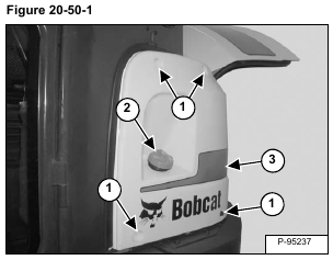
Remove the four bolts (Item 1), fuel cap (Item 2) nut and side cover (Item 3) [Figure 20-50-1].
Reinstall the fuel cap (Item 2) [Figure 20-50-1].
NOTE: Reinstall the fuel cap to prevent any contamination from entering the fuel tank.
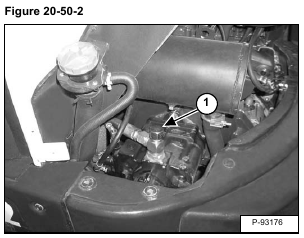
Remove the cap (Item 1) [Figure 20-50-2] from the hydraulic pump outlet.
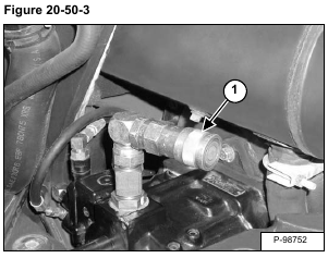
Install a test coupler (Item 1) [Figure 20-50-3] on the hydraulic pump outlet.
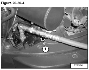
Install the hydraulic tester inlet hose (Item 1) [Figure 20-50-4] on the hydraulic pump coupler.
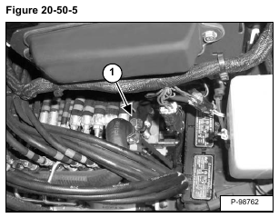
Remove the cap (Item 1) [Figure 20-50-5] from the hydraulic control valve outlet section.
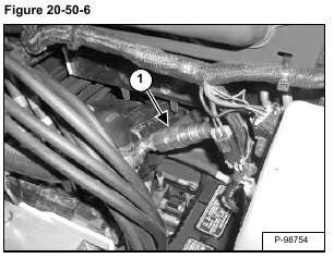
Install a test coupler (Item 1) [Figure 20-50-6] on the hydraulic control valve.
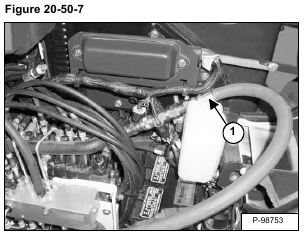
Install the hydraulic tester outlet hose (Item 1) [Figure 20-50-7] on the hydraulic control valve coupler.
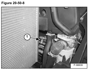
Remove the cap from the tee fitting (Item 1) [Figure 20-50-8] on the hydraulic control valve inlet section.
NOTE: If the excavator is equipped with a hydraulic X-Change, remove and plug the hose from the tee fitting.
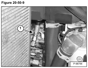
Install the adapter hose (Item 1) [Figure 20-50-9].
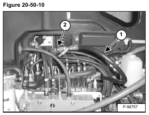
Install the jumper hose with the tee fitting (Item 1) on the hydraulic control valve outlet test port and on the adapter hose (Item 2) [Figure 20-50-10].
With the engine at high idle, turn the hydraulic tester flow control (Item 1) clockwise until 6995 kPa (69 bar) (1000 psi) is shown on the gauge (Item 2) [Figure 20-50-11].
Continue the procedure until the hydraulic oil is at a minimum of 66°C (150°F).
Test Fittings are Now Installed.
The values read at the Hydraulic Tester (MEL10003) are based on the use of 19,05 mm (0.75 in) hoses on the tester. Different size hoses will cause variation in the readings.
Turn the hydraulic tester flow control counter-clockwise until all restriction is removed.
Pump Margin Pressure Adjustment
Remove the jumper hose from the hydraulic control valve test port and adapter hose.
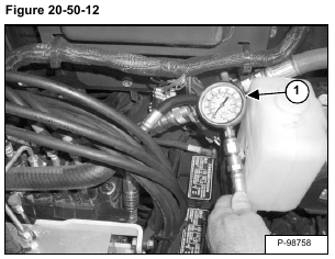
Install a 3447 kPa (34,5 bar) (500 psi) gauge on the hydraulic control valve test port (Item 1) [Figure 20-50-12].
Run the engine at High Idle.
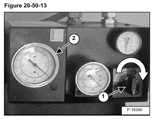
Turn the hydraulic tester flow control (Item 1) clockwise until 38 L/min (10 U.S. gpm) is shown on the gage (Item 2) [Figure 20-50-13].
Record the pressure.
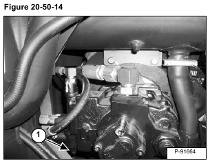
Loosen the lock nut and adjust the spool (Item 1) [Figure 20-50-14] as necessary to obtain a minimum of 1379 kPa (13,8 bar) (200 psi) on the gauge.
Pump Margin Pressure Test is now completed.
Main Relief Valve Adjustment
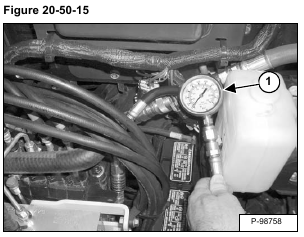
Install a 34474 kPa (345 bar) (5000 psi) (Item 1) [Figure 20-50-15] on the hydraulic control valve test port.
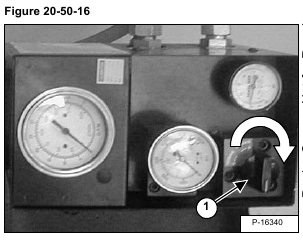
Turn the hydraulic tester flow control (Item 1) [Figure 20-50-16] clockwise until maximum restriction.
Start the engine and run at high idle.
Raise the blade until the blade cylinder is fully retracted and the relief valve opens.
Have another person check the pressure gauge and record the pressure.
The main relief valve should be 24476 ± 517 kPa (245 ± 5,2 bar) (3550 ± 75 psi).
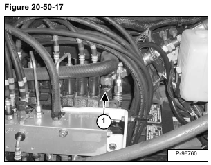
Loosen the lock nut (Item 1) [Figure 20-50-17].
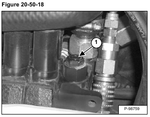
Turn the adjustment screw (Item 1) in to increase pressure and out to decrease pressure [Figure 20-50-18].
When the main relief pressure is set, tighten the lock nut.
Main Relief Valve Adjustment is now completed.
Torque Limiter Adjustment
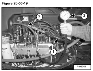
Connect a jumper hose (Item 1) to the adapter hose (Item 2) and hydraulic control valve test port. Install a
34474 kPa (345 bar) (5000 psi) gauge (Item 3) [Figure 20-50-19] on the jumper hose.
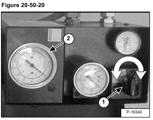
Turn the hydraulic tester flow control (Item 1) [Figure 20-50-20] counterclockwise so there is no restriction on the hydraulic system.
Start the engine and run at high idle.
If equipped with air conditioning, turn air conditioning on and turn temperature switch to the lowest setting.
Turn the hydraulic tester flow control (Item 1) [Figure 20-50-20] clockwise until the gauge (Item 3) [Figure 20-50-19] reads 8963 kPa (89,6 bar) (1300 psi).
Record the amount of flow at the tester gauge (Item 2) [Figure 20-50-20], which is the flow at low pressure.
The flow should be 87 – 95 L/min (23 – 25 U.S. gpm).
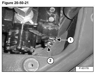
If the flow at low pressure must be adjusted, stop the engine and loosen the lock nut (Item 1). Turn the adjustment (Item 2) [Figure 20-50-21] in to increase flow and out to decrease flow.
Torque Limiter Adjustment is now completed.
Remove the hydraulic tester, all test fittings and hoses from the excavator.
Install the cap or hydraulic X-change line on the tee fitting of the hydraulic control valve inlet section.
Direct Gear Pump Test
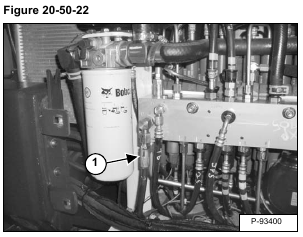
Remove the hose (Item 1) [Figure 20-50-22] from the manifold.
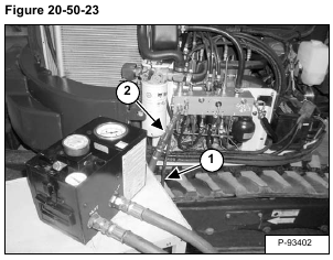
Install the inlet hose (Item 1) of the hydraulic tester to the hose removed from the manifold. Install the outlet hose (Item 2) [Figure 20-50-23] to the manifold.
Run the engine at High Idle.
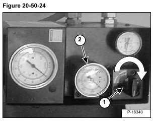
Turn the hydraulic tester flow control (Item 1) clockwise until 10342 kPa (103,4 bar) (1500 PSI) is shown on the gauge (Item 2) [Figure 20-50-24].
There must be a minimum of 7,6 L/min (2 U.S. gpm).
Remove the hydraulic tester and all test fittings from the excavator.
ALL PUMP ADJUSTMENTS ARE NOW COMPLETED.
