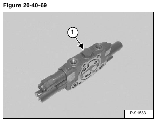
Remove the plug (Item 1) [Figure 20-40-69].
Installation: Tighten the plug to 69 – 78 N•m (51 – 58 ft-lb) torque.
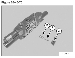
Remove the spring (Item 1) and compensator valve (Item 2). Remove the O-ring (Item 3) [Figure 20-40-70].
NOTE: The compensator valve must be installed in the valve section it was removed from.
Installing the incorrect compensator valve will cause poor hydraulic valve performance.
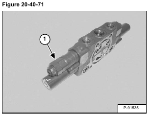
Remove the relief valve (Item 1) [Figure 20-40-71].
Installation: Tighten the relief valve to 69 – 79 N•m (51 -58 ft-lb) torque.
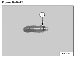
Remove the O-ring (Item 1) [Figure 20-40-72].
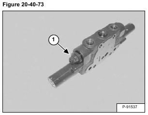
Remove the shut off valve (Item 1) [Figure 20-40-73].
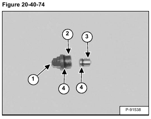
Remove the adjustment screw (Item 1) and lock nut from the valve body (Item 2). Remove the poppet (Item 3) from the body (Item 2). Remove the O-rings (Item 4) [Figure 20-40-74] from the poppet and the body.
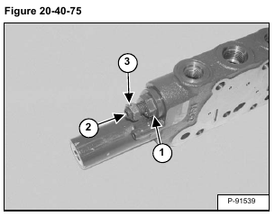
Installation: Install the poppet in the valve body. Tighten the valve body (Item 1) to 59 – 69 N•m (44 – 51 ft-lb) torque. Install the adjustment screw (Item 2). Tighten the screw to 19 – 21 N•m (14 – 15 ft-lb) torque. Install the locknut (Item 3) [Figure 20-40-75] on the adjustment screw. Tighten the nut to 19 – 21 N•m (14 – 15 ft-lb) torque.
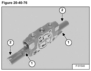
Remove the screws (Item 1) from both end caps.
Remove the end caps (Item 2) [Figure 20-40-76].
Installation: Tighten the screws to 7,5 N•m (5.5 ft-lb) torque.
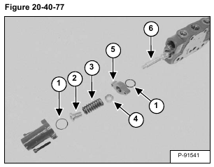
Remove the O-rings (Item 1), spring seat (Item 2), spring (Item 3), spring seat (Item 4) and spacer (Item 5) from both ends of the valve. Remove the spool (Item 6) [Figure 20-40-77].
NOTE: The spool is not symmetrical. Incorrect spool installation will cause poor hydraulic valve performance.
