Clean all parts in solvent and dry with compressed air.
Inspect all parts for wear or damage. Replace any worn or damaged parts.
Always install new seals and O-rings. Lubricate all seals and O-rings with clean hydraulic fluid before installation.
Use the following tools to assemble the cylinder:
MEL1396 – Universal Seal Expander
MEL1033 – Rod Seal Installation Tool
MEL1396-2 – Piston Ring Compressor
MEL1075 – Adjustable Gland Nut Wrench
MEL1075-1 – Standard Pins
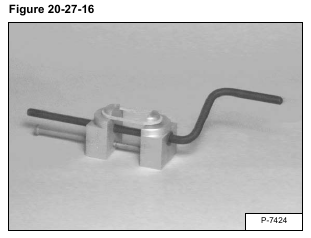
Install the new seal on the tool and slowly stretch it until it fits the piston [Figure 20-27-16].
Allow the seal to stretch for 30 seconds before installing it on the piston.
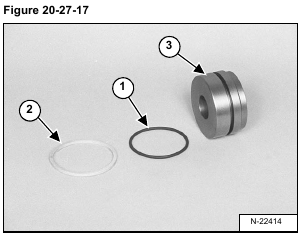
Install the O-ring (Item 1) and seal (Item 2) on the piston (Item 3) [Figure 20-27-17].
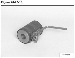
Use a ring compressor to compress the seal to the correct size. Leave the piston in the compressor for about three minutes [Figure 20-27-18].
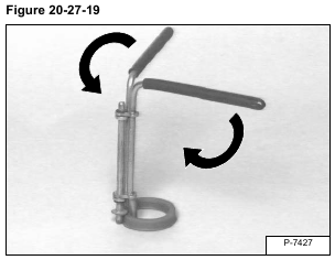
Install the rod seal on the rod seal tool [Figure 20-27-19].
NOTE: During installation the spring side of the seal must be toward the inside of the cylinder.
Rotate the handles to collapse the rod seal [Figure 20-27-19].
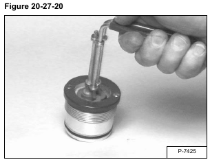
Install the rod seal in the head [Figure 20-27-20].
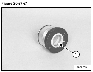
Install the wiper seal with the wiper (Item 1) [Figure 20-27-21] toward the outside of the head.
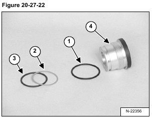
Install the O-ring (Item 1) [Figure 20-27-22].
Install the back-up ring (Item 2) and O-ring (Item 3) into the groove on the head (Item 4) [Figure 20-27-22].
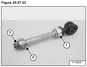
Install the head (Item 1) and the piston (Item 2) [Figure 20-27-23] on the rod as shown.
NOTE: Clean and dry the rod threads. Install a NEW NUT with pre-applied Loctite®.
Grease the piston where the nut contacts the piston. Do not get grease on the threads.
Provide an adequate support for the cylinder before tightening.
Install the nut (Item 3) [Figure 20-27-23].
Tighten the nut to 1153 N•m (850 ft-lb) torque.
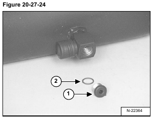
Install plug (Item 1) and O-ring (Item 2) [Figure 20-27-24].
Tighten the plug to 20 N•m (15 ft-lb) torque.
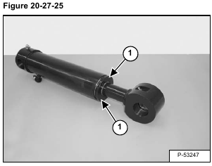
Put the base end of the hydraulic cylinder in a vise.
Insert the adjustable gland nut wrench into the two holes (Item 1) [Figure 20-27-25] to tighten the head. Head to be torqued until flush with end of housing.
