Lift and block the loader. (See LIFTING AND BLOCKING THE LOADER on Page 10-10-1.)
Raise the lift arms and install an approved lift arm support device. (See Installing Lift Arm Support Device
on Page 10-20-1.)
Raise the operator cab. (See Raising The Operator Cab on Page 10-30-1.)
Remove air cleaner. (See Removal And Installation on Page 70-40-1.)
Remove drive belt shield. (See Shield Removal And Installation on Page 30-50-1.)
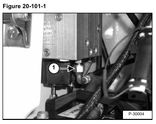
Disconnect pilot line (Item 1) [Figure 20-101-1] from diverter block.
Remove the battery. (See Removal And Installation on Page 60-20-1.)
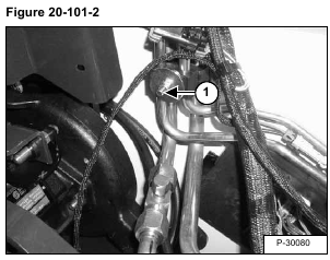
Loosen the bolt on clamp (Item 1) [Figure 20-101-2] to aid in tubeline removal.
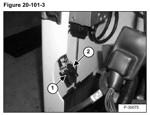
Disconnect the yellow marked frame harness (Item 1) [Figure 20-101-3] from the yellow marked diverter harness.
Disconnect the green marked frame harness (Item 2) [Figure 20-101-3] from the green marked diverter harness.
Disconnect the hose (Item 1) [Figure 20-101-4] on “F1” port.
Disconnect the hose (Item 2) [Figure 20-101-4] on the “F2” port.
Disconnect the drain hose (Item 1) [Figure 20-101-5] from the control valve.
Disconnect tubeline (Item 2) [Figure 20-101-5] from “P1” port.
Disconnect tubeline (Item 3) [Figure 20-101-5] from “P2” port.
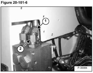
Disconnect hose (Item 1) from diverter block. Remove fitting (Item 2) [Figure 20-101-6] from diverter valve.
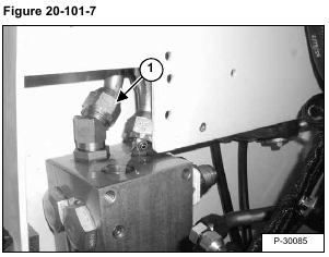
Disconnect hose (Item 1) [Figure 20-101-7] from diverter block.
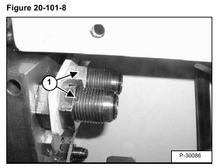
Remove jam nuts (Item 1) [Figure 20-101-8].
Remove the diverter valve from the loader.
Reverse the removal procedure to install the diverter valve.
