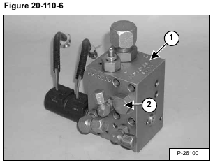
Clean the block (Item 1) [Figure 20-110-6] to remove dirt before disassembly. Block ports are labeled for correct
assembly.
Remove the plug (Item 2) [Figure 20-110-6].
Installation: Tighten the plug to 46 ft.-lbs. (62,4 Nm) torque.
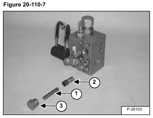
Remove the spring (Item 1) and compensator (Item 2) [Figure 20-110-7].
Check the O-ring (Item 3) [Figure 20-110-7] on the plug and replace as needed.
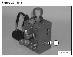
Remove the plug (Item 1) [Figure 20-110-8].
Installation: Tighten the plug to 120 in.-lbs. (13,6 Nm) torque.
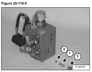
Remove the spring (Item 1) and check ball (Item 2) [Figure 20-110-9].
Check the O-ring (Item 3) [Figure 20-110-9] on the plug and replace as needed.
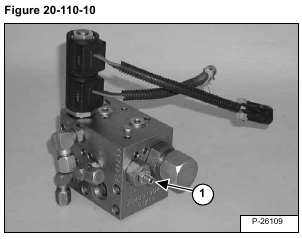
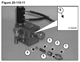
Remove the pressure reducing valve plug (Item 1) [Figure 20-110-10] & [Figure 20-110-11].
Installation: Tighten the pressure reducing valve plug to to 46 ft.-lbs. (62,4 Nm) torque.
Remove the relief piston (Item 2), spring (Item 3), ball seat spring guide (Item 4) [Figure 20-110-11].
Check the O-ring (Item 5) [Figure 20-110-11] on the pressure reducing valve plug and replace as needed.
NOTE: The relief valve seat (Item 6) [Figure 20-110-11] is a non-serviceable part. If seat is damaged, order a new power Bob-Tach block from Bobcat parts.
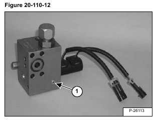
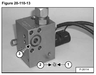
Remove the plug (Item 1) [Figure 20-110-12] & [Figure 20-110-13].
Installation: Tighten the plug to 32 in.-lbs. (3,6 Nm) torque.
Check the O-ring (Item 2) [Figure 20-110-13] on the plug and replace as needed.
Check the O-ring (Item 3) [Figure 20-110-13] and replace as needed.
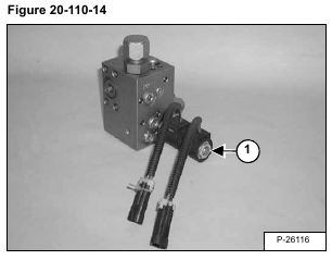
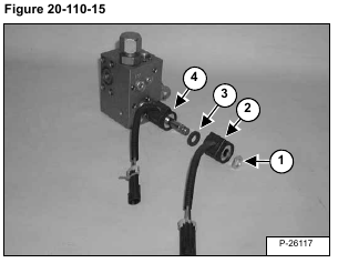
Remove the nut (Item 1) [Figure 20-110-14] & [Figure 20-110-15].
Installation: Tighten the nut to 5 ft.-lbs. (6,8 Nm) torque.
Remove the first solenoid coil (Item 2), spacer (Item 3) and the second solenoid coil (Item 4) [Figure 20-110-15].
NOTE: Remember the solenoid coil orientation for ease of installation.
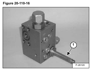
Remove the solenoid valve stem (Item 1) [Figure 20-110-16].
Installation: Tighten the solenoid valve stem to 20 ft.-lbs. (27,1 Nm) torque.
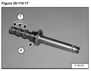
Check the O-rings and back-up washers (Item 1) [Figure 20-110-17] and replace as needed.
Installation: Put oil on O-rings and back-up washers.
Check the O-ring (Item 2) [Figure 20-110-17] and replace as needed.
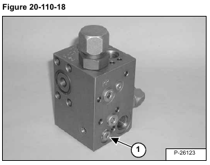
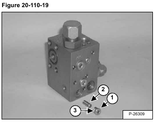
Remove the plug (Item 1) [Figure 20-110-18] & [Figure 20-110-19].
Installation: Tighten the plug to 120 in.-lbs. (13,6 Nm) torque.
Remove the dowel pin shuttle (Item 2) [Figure 20-110-19].
Check the O-ring (Item 3) [Figure 20-110-19] and replace as needed.
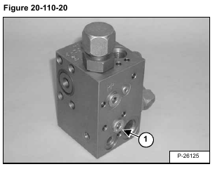
Remove the plug (Item 1) [Figure 20-110-20] & [Figure 20-110-21].
Installation: Tighten the plug to 198 in.-lbs. (22,4 Nm) torque.
Remove the pilot piston (Item 2) [Figure 20-110-21].
Check the O-ring (Item 3) [Figure 20-110-21] and replace as needed.
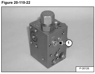
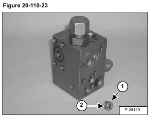
Remove the plug (Item 1) [Figure 20-110-22] & [Figure 20-110-23].
Installation: Tighten the plug to 198 in.-lbs. (22,4 Nm) torque.
Check the O-ring (Item 2) [Figure 20-110-23] and replace as needed.
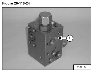
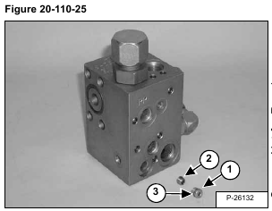
Remove the plug (Item 1) [Figure 20-110-24] & [Figure 20-110-25].
Installation: Tighten the plug to 32 in.-lbs. (3,6 Nm) torque.
Remove the orifice (Item 2) [Figure 20-110-25] with a 5/32 inch allen wrench.
Installation: Tighten the orifice to 5 ft.-lbs. (6,8 Nm) torque.
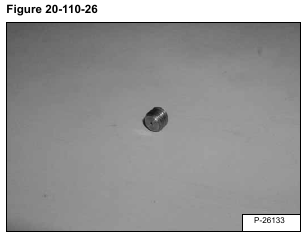
Make sure orifice is clean and not plugged [Figure 20-110-26].
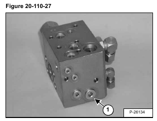
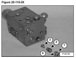
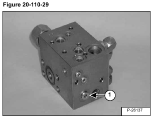
Remove the plug (Item 1) [Figure 20-110-27] & [Figure 20-110-28].
Installation: Tighten the plug to 198 in.-lbs. (22,4 Nm) torque.
Remove the relief spring (Item 2) [Figure 20-110-28].
Remove the ball seat spring guide (Item 3) [Figure 20-110-28].
Check the O-ring (Item 4) [Figure 20-110-28] and replace as needed.
Remove the plug (Item 1) [Figure 20-110-29].
Installation: Tighten the plug to 120 in.-lbs. (13,6 Nm) torque.
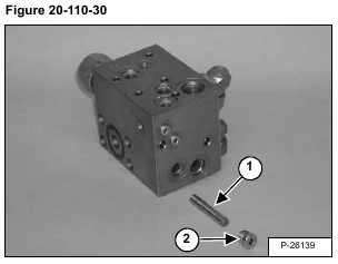
Remove the dowel pin orifice (Item 1) [Figure 20-110-30].
Check the O-ring (Item 2) [Figure 20-110-30] and replace as needed.
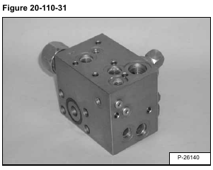
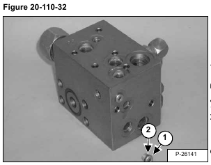
Remove the plug (Item 1) [Figure 20-110-31] & [Figure 20-110-32].
Installation: Tighten the plug to 32 in.-lbs. (3,6 Nm) torque.
Check the O-ring (Item 2) [Figure 20-110-32] and replace as needed.
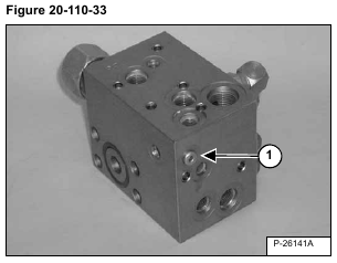
Remove the plug (Item 1) [Figure 20-110-33].
Installation: Tighten the plug to 32 in.-lbs. (3,6 Nm) torque.
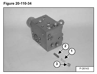
Remove the flow control spring (Item 1) [Figure 20-110-34].
Remove the flow control (Item 2) [Figure 20-110-34].
Check the O-ring (Item 3) [Figure 20-110-34] and replace as needed.
