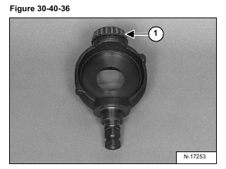
Install the lower bearing (Item 1) [Figure 30-40-36] on the swashplate.
Install the swashplate and bearing into the pump housing [Figure 30-40-37].
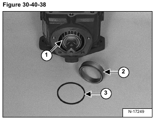
Install the tapered bearing (Item 1) [Figure 30-40-38] on the swashplate shaft.
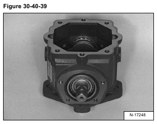
Install the bearing race (Item 2) and O-ring (Item 3) [Figure 30-40-38] as shown in [Figure 30-40-39].
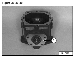
Install the upper trunnion seal (Item 1) [Figure 30-40-40] and cover.
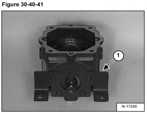
Install the steering bracket (Item 1) [Figure 30-40-41] and the four mounting bolts and tighten to 18-22 ft.-lbs.
(24-30 Nm) torque.
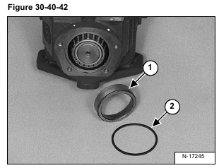
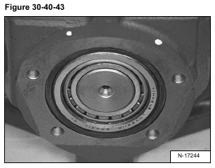
Install the bearing race (Item 1) and O-ring (Item 2) [Figure 30-40-42] at the lower trunnion as shown in
[Figure 30-40-43].
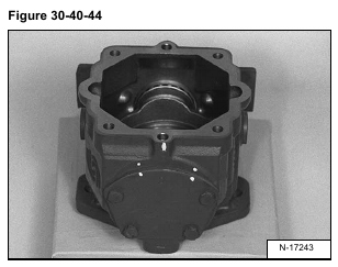
Align the marks on the lower trunnion cover and pump housing as shown in [Figure 30-40-44].
Install the four mounting bolts and tighten to 18-22 ft.-lbs. (24-30 Nm) torque.
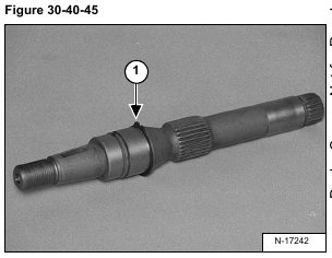
Install the snap ring (Item 1) [Figure 30-40-45] on the pump shaft.
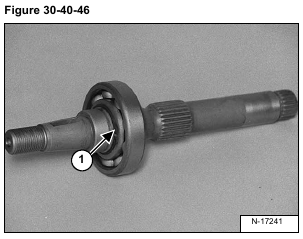
Install the bearing and snap ring (Item 1) [Figure 30-40-46] on the pump shaft.
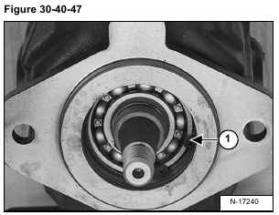
Install the pump shaft into the pump housing [Figure 30-40-47].
Install the snap ring (Item 1) [Figure 30-40-47].
Install the four slipper pins (Item 1) into the cylinder block. Use the retaining ring (Item 2) [Figure 30-40-48]
to hold the pins in place.
Apply a small amount of grease to the washer (Item 3) and install into the ball guide retainer (Item 4) [Figure 30-40-48].
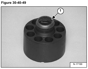
Install the ball guide retainer and washer (Item 1) [Figure 30-40-49] onto the slipper hold down pins.
Assemble the piston assemblies into the slipper guide.
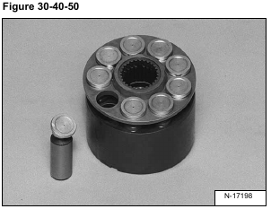
Lubricate the pistons and cylinder block bores and insert the piston assemblies into the cylinder bores [Figure 30-
40-50].
Lay the pump housing on its side and install the cylinder block, piston assembly into the housing.
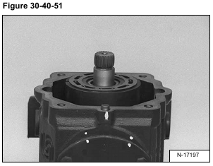
Place the pump on a work surface with the end cap opening up [Figure 30-40-51].
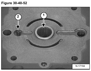
Replace the needle bearing (Item 1) and valve plate locating pin (Item 2) [Figure 30-40-52] in the pump.
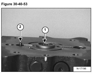
The bearing cage (Item 1) [Figure 30-40-53] will protrude from 0.08-0.10 inch (2,0-2,5 mm) from the
surface of the pump.
The valve plate locating spring pin (Item 2) [Figure 30-40-53] will protrude from 1.65-0.185 inch (4,19-4,70 mm)
from the surface of the charge pump.
Coat the backside of the valve plate with petroleum jelly to hold it in position and install the valve plate onto the
pump, bronze face up [Figure 30-40-54].
The notch (Item 1) [Figure 30-40-54] on the valve plate must engage the locating pin.
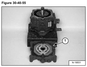
Coat a new end cap gasket (Item 1) [Figure 30-40-55] with petroleum jelly and install onto the end cap.
Install the valve plate and end cap on the pump housing.
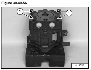
Tighten the bolts (Item 1) [Figure 30-40-56] to 35-45 ft.-lbs. (47-61 Nm) torque.
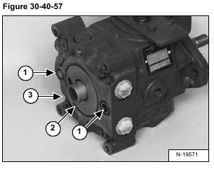
Install the two small O-rings (Item 1) [Figure 30-40-57].
Install the large new O-ring (Item 2) [Figure 30-40-57].
Install the pump coupler (Item 3) [Figure 30-40-57].
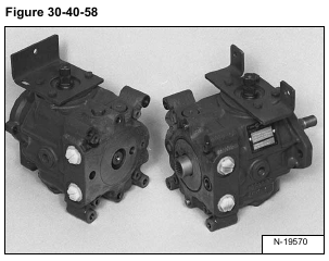
Install the two pumps together [Figure 30-40-58].
Tighten the four bolts (Item 1) [Figure 30-40-59] to 35-45 ft.-lbs. (47-61 Nm) torque.
