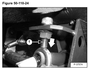
Remove access plug from the top of the control panel.
Turn the control lever drift adjustment bolts (Item 1) [Figure 50-110-17] (one on each control lever) out until it
is flush with the bottom of the nut.
Move the right side steering lever to the rear and install a 3/8 inch (10 mm) thick spacer (Item 1) between the pintle
arm cam (Item 2) and the centering block (Item 3) [Figure 50-110-18].
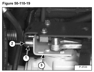
Move the right side steering lever forward and install a 15/16 inch (24 mm) thick spacer (Item 1) between the center plate (Item 2) and the mounting plate (Item 3) [Figure 50-110-19].
This will allow the pintle arms to move freely while adjusting the steering linkage for full forward travel speed.
Remove the 3/8 inch (10 mm) thick spacer (Item 1) [Figure 50-110-18].
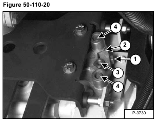
Before adjusting the linkage, check that the pintle arm mounting bolt (Item 1) is tight, 25-28 ft.-lbs. (34-38 Nm)
torque and that there is no play between the pintle arm (Item 2) and the square pump shaft (Item 3). Also check
that the cam mounting bolts (Item 4) [Figure 50-110-20] are tight, 45-50 ft.-lbs. (62-68 Nm) torque.
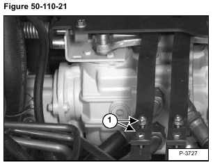
Loosen the two bolts and nuts (Item 1) [Figure 50-110-21] on each steering linkage bar.
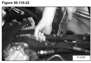
Move the left control lever to the full forward position, then pull forward on the left rear linkage bar until the pintle arm is rotated to the front as far as possible [Figure 50-110-22]. Use a locking plier and clamp the two linkage bars together.
Installation: Tighten the nuts and bolts to 25-28 ft.-lbs. (34-38 Nm) torque.
Check the lever movement to make sure that the pintle arm and the control lever are both at full stroke at the
same time. This will allow for maximum forward speed.
Repeat the procedure for the right side linkage.
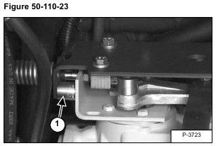
Remove the spacer (Item 1) [Figure 50-110-23].
Disconnect remote start tool. (See REMOTE START on Page 10-60-1.)

