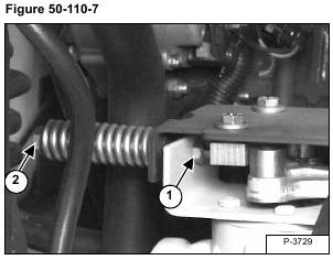
Remove the nut (Item 1) from the end of the centering spring shoulder bolt (Item 2) [Figure 50-110-7].
Remove the shoulder bolt/spring assembly.
Installation: Tighten the centering spring shoulder bolt and a NEW lock nut to 25-28 ft.-lbs. (34-38 Nm) torque.
Slide the plate (Item 1) to the right and remove it from the two guide pins (Item 2) [Figure 50-110-8].
NOTE: The two guide bushings (Item 3) will be loose and can fall out of the plate (Item 1) as soon as it is removed from the guide pins (Item 2) [Figure 50-110-8].
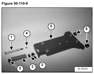
The centering plate/centering spring assembly consists of the following parts;
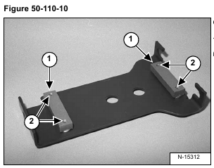
Check the wear on the centering blocks (Item 1) [Figure 50-110-10].
If the centering blocks need replacement, remove the bolts (Item 2) [Figure 50-110-10]. Remove the centering blocks.
Installation: Tighten the centering block bolts to 25-28 ft.-lbs. (34-38 Nm) torque.
If the surface of any of the four pintle cams (Item 1) are worn, loosen the bolt (Item 2) [Figure 50-110-11] and
rotate the cams 1/4 turn.
Tighten the bolts to 45-50 ft.-lbs. (62-68 Nm) torque.
When replacing the old style pintle levers, wear cams and cam bolts, install the latest style parts.
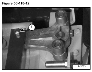
Remove the nut (Item 1) [Figure 50-110-12] from the torsion bushing/linkage bar. The bolts is threaded into the
linkage bar, remove the bolt from underneath the pintle lever.
Installation: Tighten the bolt to 11-13 ft.-lbs. (21-25 Nm) torque, then tighten the nut to 21-25 ft.-lbs. (28-33 Nm)
torque.
Remove the linkage bar (Item 1) and remove the torsion bushing (Item 2) [Figure 50-110-13].
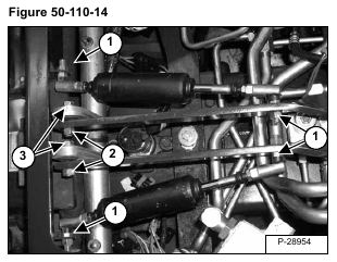
Remove the nuts (Item 1) [Figure 50-110-14] from both shock absorber ball joint ends.
Remove the shock absorbers.
Installation: Tighten the nuts to 25-28 ft.-lbs. (34-38 Nm) torque.
Remove the nuts (Item 2) from the linkage bar mounting bolt. The bolts (Item 3) are threaded into the linkage bars, remove the bolts (Item 3) [Figure 50-110-14].
The torsion bushings can now be removed from the steering bell cranks.
Installation: Tighten the bolts to 11-13 ft.-lbs. (21-25 Nm) torque, then tighten the nuts to 25-28 ft.-lbs. (34-38 Nm) torque.
Installation: Reverse the removal procedure to assemble the linkage.
The linkage and the centering plate must be readjusted for neutral after the components have been reassembled.
(See Linkage Neutral Adjustment on Page 50-110-8.)
