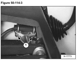
Loosen the nuts (Item 1) [Figure 50-114-3].
Installation: Tighten the u-bolts so the lever can not be moved either right or left when seated in the operator
seat. Be sure the control lever does not interfere with the operator cab when lowering or raising the cab.
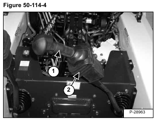
Tilt the control handle (Item 1) [Figure 50-114-4] to the center of the loader.
Lift the boot cover (Item 2) [Figure 50-114-4].
Disconnect the harness connector (Item 1) [Figure 50-114-5] from the handle sensor connector.
Disconnect the harness connector (Item 2) [Figure 50-114-5] from the handle lock solenoid connector.
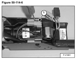
Remove the handle sensor connector (Item 1) [Figure 50-114-6] from the clip.
NOTE: Pry out with a small screw driver and push the connector down.
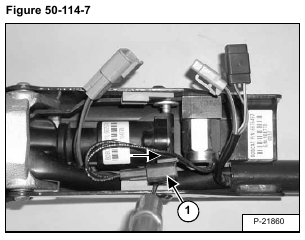
Remove the handle lock solenoid connector (Item 1) [Figure 50-114-7] from the clip.
NOTE: Pry out with a small screw driver and push the connector down.
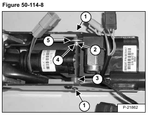
Remove one of the two mounting screws (Item 1) [Figure 50-114-8] from the handle sensor.
Installation: Tighten screws to 32-38 in.-lbs. (3,6-4,3 Nm) torque.
While removing the mounting pin (Item 2) from the handle sensor, remove the one plastic spacer (Item 3),
the spring (Item 4) and washer (Item 5) [Figure 50-114-8].
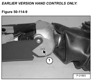
Remove the top mounting bolt (Item 1) [Figure 50-114-9] from the handle sensor.
NOTE: Be careful not to lose the recessed nut on the other side of the handle.
Installation: Tighten bolt to 32-38 in.-lbs. (3,6-4,3 Nm) torque.
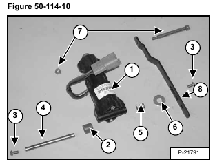
Remove the handle sensor (Item 1) [Figure 50-114-10] from the handle assembly.
NOTE: The handle sensor (Item 1) [Figure 50-114-10] can only be replaced as a complete assembly.
Check the spacer (Item 2) and screws (Item 3), mounting pin (Item 4), spring (Item 5), washer (Item 6), bolt/nut
(Item 7), stop strap (Item 8) [Figure 50-114-10] and replace as needed.
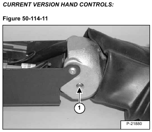
Remove one of the two mounting screws (Item 1) [Figure 50-114-11] from the handle sensor.
Installation: Tighten bolt to 32-38 in.-lbs. (3,6-4,3 Nm) torque.
Remove the handle sensor (Item 1) [Figure 50-114-12] from the handle assembly.
NOTE: The handle sensor (Item 1) [Figure 50-114-12] can only be replaced as a complete assembly.
Check the spacer (Item 2) and screws (Item 3), mounting pin (Item 4), spring (Item 5), washer (Item 6), bolt/nut
(Item 7), stop strap (Item 8) [Figure 50-114-12] and replace as needed.
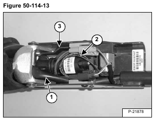
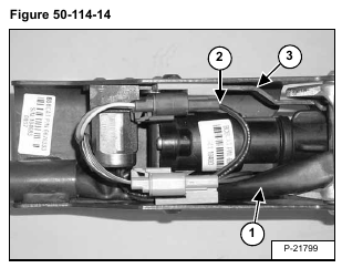
Installation: When installing the handle sensor into the control handle, check the routing of the switch handle
wire harness (Item 1) [Figure 50-114-13] & [Figure 50-114-14] to assure proper return of the control handle to
neutral and minimize harness movement.
NOTE: Route wires (Item 2) [Figure 50-114-13] & [Figure 50-114-14] as shown away from stop strap (Item 3) [Figure 50-114-13] & [Figure 50-114-14] to avoid wire damage.
NOTE: The calibration procedure must be followed when replacing handle sensor, foot pedal
sensor, actuator or ACS Controller. (See Calibration Of The ACS System on Page 60-123-14.)
