Install jackstands under the rear corners of the loader.
(See Procedure on Page 10-10-1.)
Raise the operator cab. (See Raising on Page 10-30-1.)
Remove the center control shield and the steering lever covers. See Control Shield And Steering Lever Panels Removal And Installation on Page 50-90-1
Remove the steering levers. (See Lever Removal And Installation on Page 50-100-1)
Thoroughly clean the control valve area.
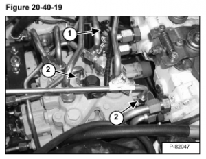
Disconnect the solenoid connector (Item 1) and remove the two tube lines (Item 2) [Figure 20-40-19] that route to the lift arm by-pass control valve.
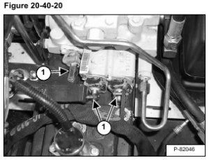
Remove the hair pins and the fastener links (Item 1) [Figure 20-40-20] from the three spools in the control valve spool.

Remove the inlet hose (Item 1) [Figure 20-40-21] from the control valve.

Remove the lift tube lines (Item 1) [Figure 20-40-22] from the control valve.
Remove the tilt tube lines (Item 2) [Figure 20-40-22] from the control valve.

Remove the auxiliary tube lines (Item 1) [Figure 20-40-23] from the control valve.
Remove the outlet tube line (Item 2) [Figure 20-40-23] from the control valve.
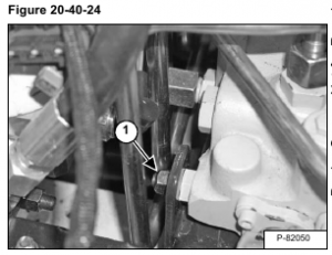
Remove the nut (Item 1) [Figure 20-40-24] from the mounting bracket on the right front corner of the control valve
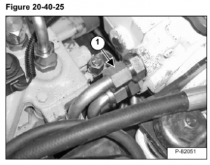
Remove the top left drive motor hose (Item 1) [Figure 20-40-25] from the hydrostatic pump.
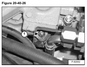
Remove the left rear mounting bolt (Item 1) [Figure 20-40-26] from the control valve.
Lift and pull the control valve forward to remove it from the loader.