Remove the control valve from the loader. (See Removal And Installation on Page 20-40-6.)
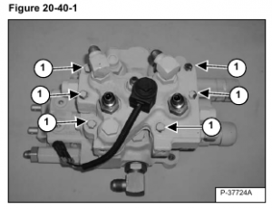
Remove the six mounting bolts (Item 1) [Figure 20-40-1] to remove the BICSTM valve from the control valve. Note the bolt locations.
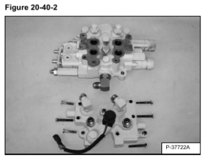
Remove the BICS valve assembly from the top of the control valve [Figure 20-40-2].
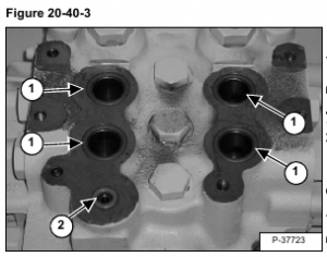
Remove and discard the four large O-rings (Item 1) and the small O-ring (Item 2) [Figure 20-40-3] from the top of the control valve.
Install new O-rings during assembly.
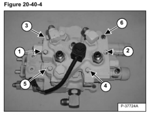
Install the six mounting bolts [Figure 20-40-4].
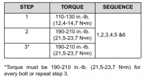
The chart below lists the correct torque specifications and tightening sequence when reinstalling the BICS valve assembly to the control valve. Thoroughly clean and dry the bolts and the threads in the valve. Use liquid adhesive LOCTITE #242 or equivalent.
