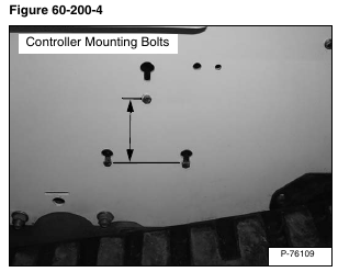
The easiest way to determine if a Bobcat controller is recent enough to add the maintenance clock is to measure the controller mounting bolt pattern on the left side of the loader mainframe. Controllers with a bolt pattern measuring 5.8 inches are maintenance clock compatible. The previous controller pattern measures 7.0 inches (not maintenance clock compatible) [Figure 60-200-4].
Using the remote start tool and service PC, connect and upgrade the Bobcat controller to version 37 or greater software. (See SERVICE PC (LAPTOP COMPUTER) on Page 60-150-1.)
If the loader is equipped with keyless panel, also update the keyless panel software.
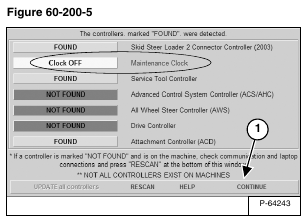
The first analyzer screen has an added bar for the Maintenance Clock. The clock will remain OFF until activated. Click Continue (Item 1) [Figure 60-200-5] to view the next analyzer screen.
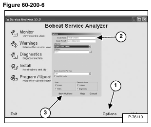
Click Options (Item 1) and add your dealer name and phone number (Item 2). Click Save Options (Item 3) [Figure 60-200-6] the information is now stored and will automatically be entered on each machine as the maintenance clock is activated. This will be displayed on keyless panel equipped loaders when the maintenance clock is less than 10 hours until next planned maintenance.
Select Install (Item 1) [Figure 60-200-7] to begin sending the dealer information to the controller.
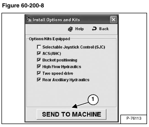
Click SEND TO MACHINE (Item 1) [Figure 60-200-8] to send the dealer information to the machine controller.
On key switch machines, during the installation process the left panel will display [InPut] (Item 1) [Figure 60-200-9] and the machine will beep twice confirming the transfer of data.
On keyless machines, during the installation process the left panel will display [InPut] (Item 1) [Figure 60-200-9], the right panel will display an icon (Item 2) [Figure 60-200-10] and the machine will beep twice confirming the transfer of data.
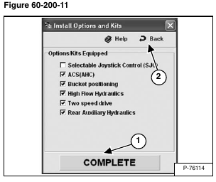
A green COMPLETE (Item 1) [Figure 60-200-11] message will be displayed when the dealer information has been transferred to the machine controller.
Click Back (Item 2) [Figure 60-200-11] to return to the Bobcat Service Analyzer screen.
Select Warnings (Item 1) [Figure 60-200-12].
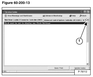
Click the right arrow (Item 1) [Figure 60-200-13] to scroll through the tabs.
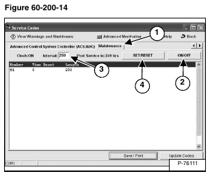
NOTE: The Maintenance tab (Item 1) [Figure 60-200-14] will not appear when servicing loaders
equipped with the older controller.
Click the Maintenance tab (Item 1) [Figure 60-200-14] to view the maintenance clock screen.
Click ON/OFF (Item 2) to turn the maintenance clock on or off [Figure 60-200-14].
The default Interval (Item 3) is 250 hours, it can also be changed by placing the cursor in the box and typing the new interval. Click SET/RESET (Item 4) [Figure 60-200-14] to reset and set the maintenance clock.
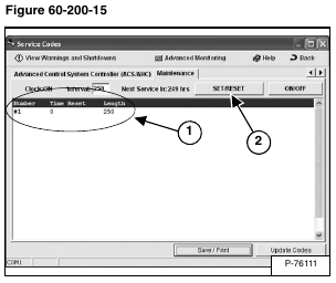
The current maintenance clock Length (Interval) and Time Reset will be displayed (Item 1). This screen will also store the most recent 20 entries of history. Once an entry is added, it can not be changed. If an entry is made and the interval is not correct, make another entry and click SET/RESET (Item 2) [Figure 60-200-15].
NOTE: If the interval is set to 10 hours or less, the maintenance clock will reset and log a reset time but the wrench icon, alternating hour interval and [SEr] will NOT be removed from the left and right instrument panel display screens.
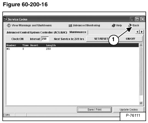
Select Back (Item 1) [Figure 60-200-16] to return to the main menu.
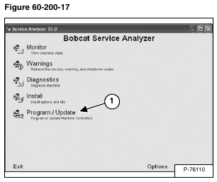
Select Program / Update (Item 1) [Figure 60-200-17] to view the maintenance clock.
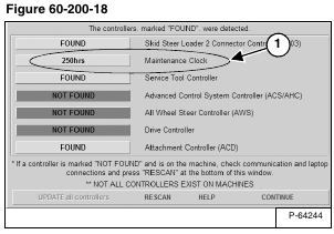
After the maintenance clock has been activated, the first analyzer screen shows the hours remaining on current maintenance interval (Item 1) [Figure 60-200-18]. If past the interval, the number will reflect negative hours.
