Roll the Bob-Tach fully forward. Stop the engine.
Remove the Bob-Tach frame from the lift arms. (See Removal And Installation on Page 50-40-1.)
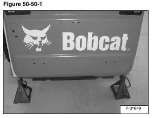
Install jackstands under the rear of the loader [Figure 50-50-1].
Left Side
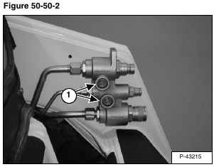
Remove the front auxiliary block mounting bolts (Item 1) [Figure 50-50-2].
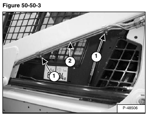
Remove the tubeline clamps (Item 1) [Figure 50-50-3] under the lift arms.
Pull the tubelines (Item 2) [Figure 50-50-3] down.
Right Side
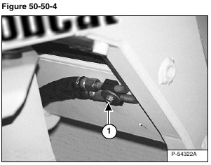
Remove the mounting bolt (Item 1) [Figure 50-50-4] from the tilt tubeline clamp.
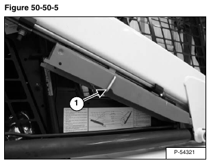
Remove the lift arm support device (Item 1) [Figure 50-50-5].
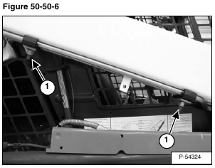
Remove the tubeline clamps (Item 1) [Figure 50-50-6] under the lift arms.
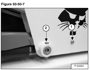
Remove the lift arm support device mounting bolt (Item 1) [Figure 50-50-7] spacer and nut.
Installation: Tighten the mounting bolt and nut to 25 – 28 ft.-lb. (34 – 38 N•m) torque.
Remove the retainer bolt (Item 2) [Figure 50-50-7] and nut from the lift cylinder rod end pivot pin.
Installation: Tighten the mounting bolt and nut to 25 – 28 ft.-lb. (34 – 38 N•m) torque.
Raise the operator cab. (See Raising on Page 10-30-2.)
Remove the right side lift cylinder pivot pin (Item 1) [Figure 50-50-8].
NOTE: Put a piece of cardboard under the rod end of the lift cylinders to protect the fender from scratches.
Remove the lift arm support device (Item 2) [Figure 50-50-8].
Remove the left side lift cylinder pivot pin (Item 1) [Figure 50-50-9].
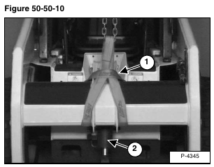
Wrap one of the 7 ft. lifting straps around the lift arm crossmember as shown [Figure 50-50-10].
Both loops of the lifting strap should be supported by the chain hoist [Figure 50-50-10].
Use a chain hoist and lifting strap to raise the lift arms enough to remove the tilt cylinder base end pivot pin (Item 1) [Figure 50-50-10].
Remove the tilt cylinder (Item 2) [Figure 50-50-10] from the lift arm crossmember and put on the blocking.
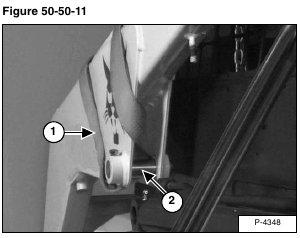
Put the middle of the second lifting strap (Item 1) [Figure 50-50-11] up into the lift arm as shown.
Install the lift cylinder pivot pin (Item 2) [Figure 50-50-11] and secure the pin with the mounting bolt and nut.
Wrap both ends of the strap around the top of the lift arm and down the back of the lift arm [Figure 50-50-11].
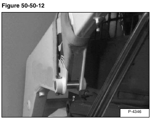
Continue to wrap the lifting strap around the lift arm a second time [Figure 50-50-12].
Fasten both loops of the lifting strap to a second chain attached to the chain hoist.
Use the wrapping procedure on the third strap which should be installed on the right side lift arm.
Use the chain hoist and lower the lift arms so they rest on the blocking.
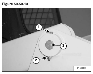
Remove the upright pivot pin mounting bolt (Item 1) [Figure 50-50-13] and nut (Item 2) [Figure 50-50-13]. (Both sides.)
Installation: Tighten the pivot pin mounting bolt and nut to 25 – 28 ft.-lb. (34 – 38 N•m) torque.
Remove the upright pivot pin (Item 3) [Figure 50-50-13]. (Both sides.)
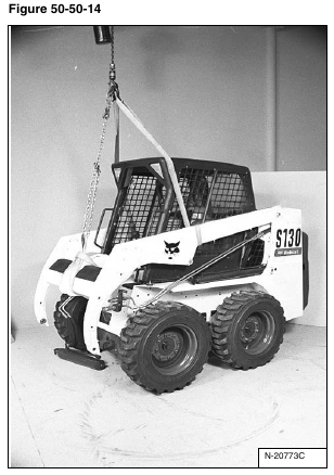
Raise the lift arms with the chain hoist so the lift arms are free from the loader [Figure 50-50-14].
Pull the lift arms away from the loader [Figure 50-50-15].
Lower the lift arms slowly and put on the floor.
Reverse the removal procedure to install the lift arms on the loader.
