Raise the operator cab. (See Raising on Page 10-30-2.)
Remove the front and rear wheel/tire assemblies. (See TIRE MAINTENANCE on Page 10-160-1.)
Raise the lift arms and install an approved lift arm support device. (See Installing on Page 10-20-1.)
Lift and block the loader. (See Procedure on Page 10-10-1.)
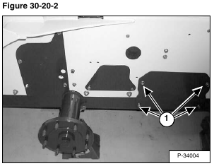
Remove the four motor cover mounting screws (Item 1) [Figure 30-20-2].
Installation: Tighten screws to 15 – 20 ft.-lb. (20 – 27 N•m) torque.
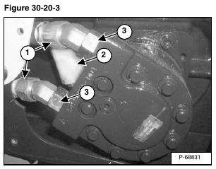
Mark the two hoses (Item 1) [Figure 30-20-3] before disconnecting them from the hydrostatic motor for correct installation.
Remove the two hoses (Item 1) [Figure 30-20-3] from the hydrostatic motor.
Remove the drain hose and case drain filter (Item 2) [Figure 30-20-3] from the hydrostatic motor.
NOTE: The hydraulic fittings (Item 3) [Figure 30-20-3] on the hydrostatic motor must be tightened to 115 – 125 ft.-lb. (156 – 170 N•m) torque.
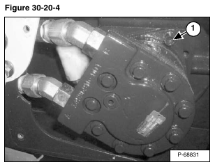
Remove the four hydrostatic motor mounting bolts (Item 1) [Figure 30-20-4] that fasten the hydrostatic motor to the hydrostatic motor carrier.
Installation: Tighten the hydrostatic motor mounting bolts to 90 – 100 ft.-lb. (122 – 136 N•m) torque.
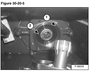
Remove the hydrostatic motor from the access hole in the loader frame [Figure 30-20-5].
Inspect hydrostatic motor O-ring (Item 1) and carrier shaft seal (Item 2) [Figure 30-20-5].
Reverse the removal procedure to install the hydrostatic motor.


