Drain the oil from the motor.
Seal all open ports and clean the motor with solvent.
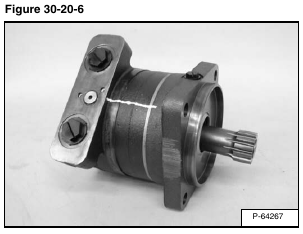
Put a mark across the sections of the motor for correct assembly [Figure 30-20-6].
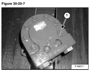
Remove the nine tie bolts (Item 1) [Figure 30-20-7] from the motor.
Assembly:
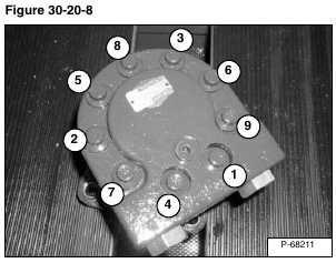
1. Tighten the bolts to 45 – 55 ft.-lb. (61 – 75 N•m) torque in the order shown in figure [Figure 30-20-8].
2. Re-tighten the bolts to 55 – 65 ft.-lb. (75 – 88 N•m) torque in the order shown in figure [Figure 30-20-8].
NOTE: To prevent damage to the balance plate, never lift or support the motor by the drive shaft.
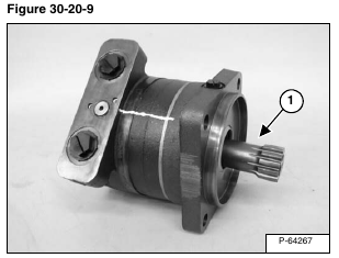
Once the tie bolts have been removed and the motor begins to separate, the drive shaft (Item 1) [Figure 30-20-9] can be removed.
Assembly: Install drive shaft before tightening tie bolts.
Lift and remove the end cap (Item 1) [Figure 30-20-10] from the motor.
NOTE: Do not scratch or damage the surfaces of the motor sections. Always put them on a soft surface.
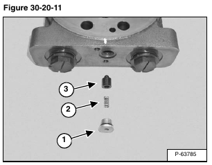
Remove the plug (Item 1) spring (Item 2) and poppet (Item 3) [Figure 30-20-11] that make up the relief valve assembly. Inspect for scoring on poppet. Ensure it can operate freely in the bore. Inspect O-ring on plug.
Installation: Lubricate relief valve assembly with hydraulic oil and tighten plug to 260 in.-lb. (41 N•m) torque.
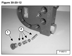
Remove the plug (Item 1) and shuttle valve assembly (Item 2) [Figure 30-20-12]. Inspect for scoring on shuttle valve. Ensure it can operate freely in the bore. Inspect O-ring on plug.
Installation: Lubricate shuttle valve assembly with hydraulic oil and tighten plug to 260 in.-lb. (41 N•m) torque.
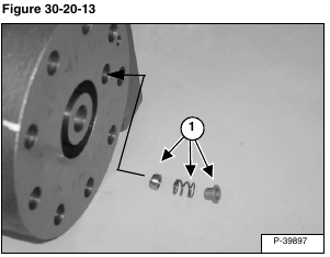
Remove the remaining pieces to the shuttle valve assembly (Item 1) [Figure 30-20-13] from the inside of the end cap. Inspect for broken or damaged parts. Parts should move freely in bore.
Assembly: Apply grease to shuttle valve parts to help hold in place during assembly.
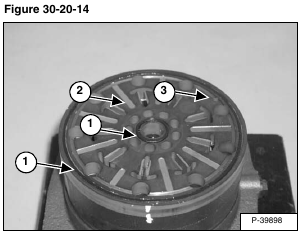
Remove and inspect/replace seals (Item 1) [Figure 30-20-14].
Remove the valve plate (Item 2) [Figure 30-20-14].
Assembly: Apply grease to seals. Note location of case drain hole (Item 3) [Figure 30-20-14]. Align hole with other sections on hydrostatic motor.
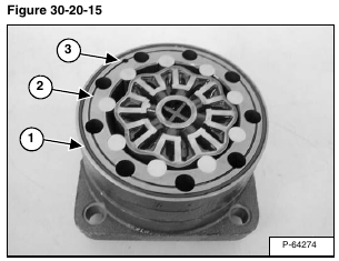
Remove and inspect/replace seal (Item 1) [Figure 30-20-15].
Remove the geroler section as an assembly (Item 2) [Figure 30-20-15].
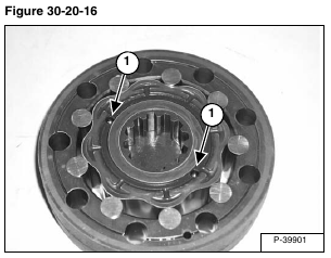
NOTE: There are two check balls on the backside of the geroler section. Be careful not to lose these check balls. See [Figure 30-20-16]. Note location of case drain hole (Item 3) [Figure 30-20-15]. Align hole with other sections on hydrostatic motor.
Remove the two check balls (Item 1) [Figure 30-20-16] from the geroler.
Assembly: Check for scoring and wear on the geroler assembly. Apply grease to check balls to keep them from falling out of there seats when assembling.
NOTE: Care should be taken to keep the geroler assembly together.
NOTE: If rollers are removed, put them back in their original bore.
Remove the center piece of the balance plate (Item 1) [Figure 30-20-17].
Remove and inspect/replace the seal (Item 2) [Figure 30-20-17].
Remove the balance plate (Item 3) [Figure 30-20-17].
Assembly: Apply grease to seals. Note location of case drain hole (Item 4) [Figure 30-20-17]. Align hole with other sections on hydrostatic motor.
Remove the back up ring (Item 1) [Figure 30-20-18].
Assembly: Apply grease to back up ring. One side of the back up ring is grooved to fit against the o-ring underneath.
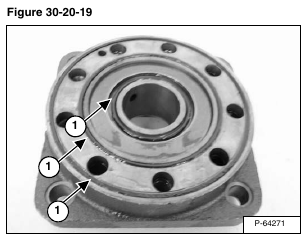
Remove and inspect/replace the seals (Item 1) [Figure 30-20-19] from the geroler.
Assembly: Apply grease to seals.
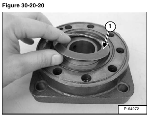
Remove the belleville spring. (Item 1) [Figure 30-20-20].
Assembly: If the belleville spring is no longer cone shaped, replace with new.
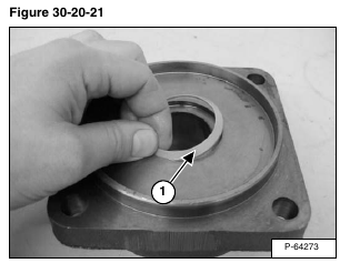
Carefully turn the mounting flange over and remove the seal (Item 1) [Figure 30-20-21].
Assembly: Replace the seal.
