Raise the lift arms and install an approved lift arm support device. (See Installing on Page 10-20-1.)
Raise the operator cab.(See Raising on Page 10-30-2.)
Remove the fan motor/charge pump filter housing. (See Charge Filter Housing Removal And Installation on Page 20-80-3.)
Remove the hydraulic fluid reservoir. (See Removing And Replacing Hydraulic Fluid on Page 10-120-2.)
Remove cable ties (Item 1) [Figure 70-50-9] attached to blower housing.
Disconnect and plug the heater hoses (Item 2) [Figure 70-50-9].
Disconnect the cab harness connector (Item 3) [Figure 70-50-9].
Remove the sealant between the blower housing and the loader frame (Item 4) [Figure 70-50-9].
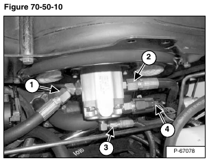
Remove the fan motor inlet hose (Item 1) and outlet hose (Item 2) [Figure 70-50-10].
Remove the fan motor case drain hose (Item 3) [Figure 70-50-10].
Disconnect the electrical connector (Item 4) [Figure 70-50-10].
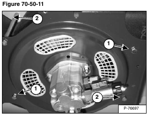
NOTE: Remove the two rear mounting bolts first.
Remove the four mounting bolts (Item 1 and Item 2) and spacer tubes. The only visible spacer tubes are on the outside of the blower housing using mounting bolts (Item 2) [Figure 70-50-11].
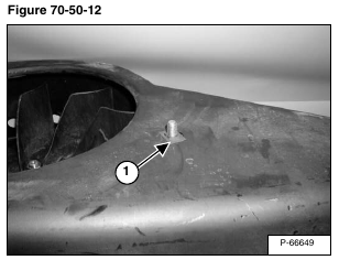
NOTE: The picture shows the blower housing and fan assembly removed from the loader. Two of the mounting bolts (Item 1) [Figure 70-50-11] have clips (Item 1) [Figure 70-50-12] to hold the bolts from falling out during factory installation of the blower housing and fan together. The clips will fall during the removal of the fan motor assembly bolts.
Remove the blower housing from the loader.
Reverse the removal procedure to install the blower housing.
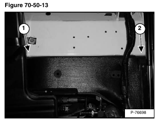
After the blower housing is installed, apply a bead of polyurethane caulk sealant (P/N 6633583) between the front edge (Item 1) of the crossmember and blower housing (Item 2) [Figure 70-50-13] directly in front of the inlet opening only.


