When installing the new switch handle, tape the wire terminals together.
The switch handle comes with a 6 inch piece of heat shrink tubing placed over the end of the wires. Remove the heat shrink tube from the end of the wires before routing the harness through handle and control lever tube.
NOTE: Leave all the other heat shrink tube on the wires for protection.
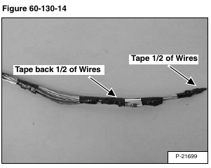
Tape half of the wires back and half forward [Figure 60-130-14] to keep the harness small enough to route through the control lever tube.
Install the new switch handle and wires from the top of the control lever.
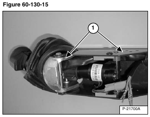
Route wire (Item 1) [Figure 60-130-15] through the casting, along side the handle sensor and into the control lever tube.
NOTE: Do not pull the wire harness tight. Allow a small amount of slack or slight bend at the handle pivot area. Verify the control handle returns to neutral position.
Remove tape from wires for installation and install the 6 inches of heat shrink tube (Item 1) [Figure 60-130-16] approximately 3 inches into the control lever. Apply heat to the exposed heat shrink tube.
Inspect the wire terminal tabs (Item 2) [Figure 60-130- 16] and re-bend tabs if necessary.
Install the wires into the connectors as listed below:
Right Switch Handle
Ten-Pin Connector
A-Terminal – Orange
B-Terminal – White
C-Terminal – White/Black
D-Terminal – White/Red
E-Terminal – Dk. Green
F-Terminal – White/Lt. Green
G-Terminal – Yellow/Red
H-Terminal – Lt. Green
J-Terminal – Yellow
K-Terminal – Orange/Black
Three-Pin Connector
A-Terminal – Red/White
B-Terminal – Black/White
C-Terminal – Purple/White
Left Switch Handle
Ten-Pin Connector
A-Terminal – Orange
B-Terminal – Dk. Blue
C-Terminal – White
D-Terminal – Purple
E-Terminal – Yellow/Red
F-Terminal – Tan
G-Terminal – Pink
H-Terminal – Orange/Black
J-Terminal – Blank
K-Terminal – Blank
Three-Pin Connector
A-Terminal – Red/White
B-Terminal – Black/White
C-Terminal – Purple/White
Two-Pin Connector
A-Terminal – Black
B-Terminal – Red
Five-Pin Connector
A-Terminal – Dk. Green
B-Terminal – Brown
C-Terminal – Blank
D-Terminal – Yellow
E-Terminal – Blank
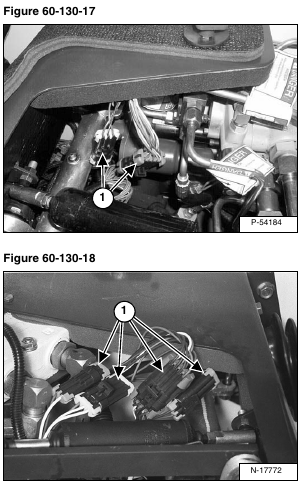
Connect the handle harness connectors (Item 1) [Figure 60-130-17] & [Figure 60-130-18] to the loader harness connectors.
Install the wires into the connectors as listed below:
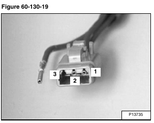
Left and Right Control Lever Switch Handle [Figure 60-130-19]
1-Terminal – Red/White
2-Terminal – Black/White
3-Terminal – Purple/White
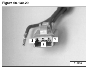
Left and Right Control Lever Switch Handle [Figure 60-130-20]
1-Terminal – Yellow/Red
2-Terminal – Open
3-Terminal – Orange/Black
Connect the handle harness connectors to the sensor and lock solenoid connectors [Figure 60-130-21].
