Raise the loader lift arms and install an approved lift arm support device. (See Installing on Page 10-20-1.)
Raise the loader operator cab. (See Raising on Page 10-30-2.)
Disconnect and remove the engine speed control. (See Removal And Installation on Page 70-20-1.)
Remove the control panel from the loader. (See Removal and Installation on Page 50-100-2.)
Remove the center chaincase cover. (See Center Cover Removal And Installation on Page 40-30-2.)
Remove the traction lock assembly. (See Removal And Installation on Page 60-120-2.)
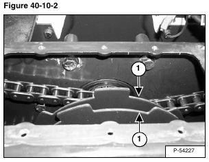
The parking brake discs (Item 1) [Figure 40-10-2] are located beneath the center chaincase cover.
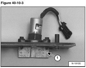
Inspect the traction lock guides (Item 1) [Figure 40-10-3] and the brake disc for damage or wear and replace as necessary. (See Inspecting on Page 60-120-6.)
A snap ring pliers with 90 degree tips are necessary for removing the parking brake disc.
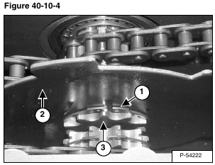
Remove the snap ring (Item 1) from the end of the sprocket (Item 2) [Figure 40-10-4] on the hydrostatic motor carrier.
Slide the disc (Item 3) [Figure 40-10-4] off the sprocket and remove the disc.
Reverse the removal procedure to install the disc in the loader.


