Lift and block the loader. (See Procedure on Page 10-10-1.)
Raise the lift arms and install an approved lift arm support device. (See Installing on Page 10-20-1.)
Raise the operator cab. (See Raising on Page 10-30-2.)
Open the rear door.
Drain the hydraulic reservoir. (See Removing And Replacing Hydraulic Fluid on Page 10-120-2.)
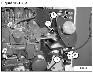
Remove the nut from the speed control linkage (Item 1) and unplug the rear lights electrical connector (Item 2) [Figure 20-130-1].
Remove the fuel fill bracket mounting screws (Item 3) [Figure 20-130-1].
Installation: Tighten screws to 15 – 20 ft.-lb. (20 – 27 N•m) torque.
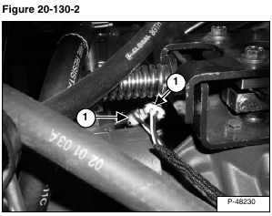
Disconnect the power Bob-Tach harness from the solenoid connectors (Item 1) [Figure 20-130-2] by the hydraulic pump.
Installation: The harness connectors are marked with Red or Black tie straps. Be sure the connectors with the same color are connected.
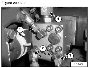
Disconnect the hose (Item 1) [Figure 20-130-3] from the “DR” port fitting on the block.
Disconnect the hose (Item 2) [Figure 20-130-3] from the power Bob-Tach cylinder rod end fitting on the block.
Disconnect the hose (Item 3) [Figure 20-130-3] from the power Bob-Tach cylinder base end fitting on the block.
Disconnect the outlet hose (Item 4) [Figure 20-130-3] from the fitting on top of the block.
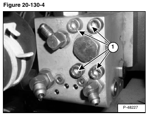
Remove the four mounting bolts (Item 1) [Figure 20-130-4].
Installation: Tighten the mounting bolts to 25 – 28 ft.-lb. (34 – 38 N•m) torque.
Remove the power Bob-Tach block.
NOTE: There is an O-ring in-between the power Bob-Tach block and the hydraulic pump. Inspect and replace as needed.


